


16 - FORM NO. 56041704
American-Lincoln
6150
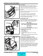
SIDE BROOM LEVER
The side broom lever is located on the right side of
the instrument panel. The side broom lever raises and
lowers the side broom. Use the brooms lever on the
operator’s center console to turn on the side broom.
To raise the side broom, pull the lever back into the “UP”
position.
To lower the side broom, move the lever out of the
detented “UP” position and move it forward to the
“DOWN” position.
SIDE BROOM ADJUSTMENT
The side broom lever has an adjustment for changing
the sweep height to compensate for broom wear. The
side broom adjustment is located under the right side of
the instrument panel.
To Adjust the side broom height turn the threaded knob.
MAIN BROOM LEVER
The main broom lever is located on the left side of
the instrument panel. The main broom lever has three
positions and controls the main broom sweep height.
Use the brooms lever on the operator’s center console to
turn on the main broom.
To lower the main broom, grasp the lever and move
it to the left out of the “UP” position and place in the
“SWEEP” or “FLOAT” position.
The “SWEEP” position is used for normal sweeping and
should be used under most sweeping conditions.
The “FLOAT” position is used for sweeping very uneven
surfaces only. Using the Float position will cause
premature wear on the main broom if used under normal
operating conditions for extended periods of time.
MAIN BROOM ADJUSTMENT
The main broom lever has an adjustment for changing
the sweep height to compensate for broom wear. The
main broom adjustment is located under the left side of
the instrument panel.
To Adjust the main broom height turn the threaded knob.
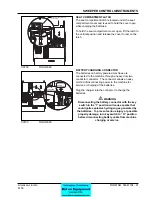
SWEEPER CONTROLS/INSTRUMENTS
SIDE BROOM
UP
DOWN
0
1/2
4/4
FUEL
SIDE BROOM
LEVER
SIDE BROOM
ADJUSTMENT
LIGHTS
WORK
LIGHT
GLOW
PLUG
MAIN BROOM
FLOAT
SWEEP
UP
HOURS
0 0 0 0 0
1/10
MAIN BROOM
LEVER
MAIN BROOM
ADJUSTMENT
C-0721
C0721
FIGURE 16
C0720
FIGURE 15
Содержание 6150
Страница 39: ...FORM NO 56042480 6150 IC 4 06 5 REAR WHEEL 07 10 ...
Страница 41: ...FORM NO 56042480 6150 IC 6 06 5 VAC FAN 07 10 ...
Страница 45: ...FORM NO 56042480 6150 IC 10 06 5 FLAP ASSEMBLY WHEEL WELL 07 3 C 1227 ...
Страница 51: ...FORM NO 56042480 6150 IC 16 06 5 C1250 H46 H43 H39 H47 H53 SIDE BROOM ASSEMBLY 07 3 ...
Страница 53: ...FORM NO 56042480 6150 IC 18 06 5 SIDE BROOM LIFT SYSTEM 07 10 ...
Страница 55: ...FORM NO 56042480 6150 IC 20 06 5 SIDE BROOM LEVER 07 3 H50 H54 H35 H46 H54 H85 H113 H52 C 1218 ...
Страница 57: ...FORM NO 56042480 6150 IC 22 06 5 BROOM CHAMBER FLAPS SEALS 07 10 ...
Страница 59: ...FORM NO 56042480 6150 IC 24 06 5 BRAKE PEDAL 80805 1 6 05 07 3 ...
Страница 63: ...FORM NO 56042480 6150 IC 28 06 5 SEAT FLOOR ASSEMBLY 07 10 ...
Страница 71: ...FORM NO 56042480 6150 IC 36 06 5 CONTROL RELIEF VALVE 3 CYL KUBOTA GAS DIESEL 07 3 ...
Страница 73: ...FORM NO 56042480 6150 IC 38 06 5 FWD REV CONTROL 2 CYL KAWASAKI GAS 07 10 ...
Страница 75: ...FORM NO 56042480 6150 IC 40 06 5 FW REV CONTROL 3 CYL KUBOTA GAS DIESEL 07 3 ...
Страница 79: ...FORM NO 56042480 6150 IC 44 06 5 C1222A2 TORQUE HOSE CLAMPS 21 25 FT LBS RESERVOIR 3 CYL KUBOTA GAS DIESEL ...
Страница 81: ...FORM NO 56042480 6150 IC 46 06 5 FUEL TANK GAS 07 10 ...
Страница 83: ...FORM NO 56042480 6150 IC 48 06 5 FUEL TANK DIESEL 07 10 ...
Страница 87: ...FORM NO 56042480 6150 IC 52 06 5 80806 2 2 05 HOPPER COVERS GASKET ASSEMBLY ...
Страница 91: ...FORM NO 56042480 6150 IC 56 06 5 H26 H80 H86 H26 H98 H22 C 1207 9701 DUMP DOOR ...
Страница 97: ...FORM NO 56042480 6150 IC 62 06 5 HYDRAULIC PUMP 3 CYL KUBOTA GAS DIESEL 07 3 80851 SHT01 ...
Страница 99: ...FORM NO 56042480 6150 IC 64 06 5 ENGINE COVER 30 25 32 31 80813 0 3 07 ...
Страница 101: ...FORM NO 56042480 6150 IC 66 06 5 80841 8 05 ACCESS COVER ASSEMBLY ...
Страница 105: ...FORM NO 56042480 6150 IC 70 06 5 ENGINE 3 CYL KUBOTA GAS 07 10 ...
Страница 107: ...FORM NO 56042480 6150 IC 72 06 5 ENGINE 3 CYL KUBOTA DIESEL 07 10 ...
Страница 109: ...FORM NO 56042480 6150 IC 74 06 5 ENGINE 3 CYL DUAL FUEL LP 07 10 ...
Страница 113: ...FORM NO 56042480 6150 IC 78 06 5 80839revF 8 05 HYDRAULIC HOSE DIAGRAM 2 CYL ...
Страница 125: ...FORM NO 56042480 6150 IC 90 06 5 DECALS 08 7 ...
Страница 127: ...FORM NO 56042480 6150 IC 92 06 5 DECALS continued 07 10 ...
Страница 129: ...FORM NO 56042480 6150 IC 94 06 5 C1335 7 04 2 CYLINDER LP CE MODELS ONLY ...
Страница 136: ...101 FORM NO 56042480 6150 IC 06 5 HYDRAULIC SCHEMATIC 2 CYL GAS LP DIESEL 08 7 ...
Страница 138: ...103 FORM NO 56042480 6150 IC 06 5 HYDRAULIC SCHEMATIC 3 CYL KUBOTA GAS DIESEL ...