


American-Lincoln
FORM NO. 56041704 - 25
6150
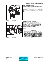
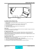
TO START DIESEL ENGINE
When starting the diesel engine, it should be noted that under no circumstances should Ether or any other
starting fl uids be used in conjunction with the glow plugs. Do not use the glow plugs for more than 60 seconds
at a time or damage to the plugs may result. They key switch must be placed in the “ON” position before using
the glow plug switch.
1. Perform the Pre-Start checks found previously in this manual.
2. Turn the ignition switch to the “ON” position and place the throttle in a high engine speed setting.
3. Push and hold the glow plug switch for approximately 30 seconds. Under cold starting conditions, the
glow plug switch may be held longer but do not hold the switch for more than 60 seconds to prevent
damage to the glow plugs.
4. Turn the key switch to the start position and hold until engine starts. If the engine does not start
immediately, release the key switch after 15 seconds to prevent damage to the starter.
5. Release the glow plug switch when the engine starts.
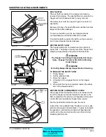
TO DRIVE SWEEPER FOR TRANSPORT
1. Ensure the main broom lever and the side broom lever are in “UP” position with all other sweeping
controls in the “OFF” position.
2. Release the parking brake.
3. Adjust the throttle to a medium to high engine speed setting.
4. Push forward on the foot pedal to start the sweeper moving.
5. Vary your foot pressure on the pedal to obtain the desired speed.
6. To stop, allow the foot pedal to return to the centered position. (Pedal will return to neutral when pressure
is released)
WARNING
Do Not Turn The Steering Wheel Sharply When The Machine Is In Motion. The Sweeper Is Very
Responsive To Movement Of The Steering Wheel. Do Not Make Sudden Turns.
WARNING
Machines Can Ignite Flammable Materials And Vapors. Do Not Use With Or Near Flammables Such As:
Gasoline, Grain Dust, Solvents And Thinners.
TO SWEEP WITH THE MACHINE
1. Move the broom control lever to the “ON” position.
2. Lower the side and main broom to the fl oor. (The main broom control may be placed in either the “FLOAT”
or “SWEEP” position).
3. Press the Dust Control Switch to the “ON” position.
4. Push forward on directional control pedal to place machine in motion.
5. Vary foot pressure on the directional control pedal to obtain desired travel speed.
6. Read the “Helpful Hints for Sweeping” in this manual for tips on maximizing sweeping performance.
WARNING
Stop And Leave This Machine On A Level Surface. When You Stop The Machine, Put The Key Switch
In The “OFF” Position And Engage The Parking Brake.
TO STOP SWEEPING
1. Allow directional control pedal to return to neutral (centered) position. (Pedal will automatically return to
neutral when foot pressure is released.)
2. Depress the foot brake.
3. Press the Dust Control Switch to the “OFF” position..
4. Place the broom controls (Side and Main) in the “UP” position.
5. Move the Broom Control lever to the center “OFF” position.
6. Adjust the throttle to a low engine speed setting.
7. Set parking brake.
OPERATING INSTRUCTIONS
Содержание 6150
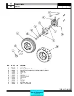
Страница 39: ...FORM NO 56042480 6150 IC 4 06 5 REAR WHEEL 07 10 ...
Страница 41: ...FORM NO 56042480 6150 IC 6 06 5 VAC FAN 07 10 ...
Страница 45: ...FORM NO 56042480 6150 IC 10 06 5 FLAP ASSEMBLY WHEEL WELL 07 3 C 1227 ...
Страница 51: ...FORM NO 56042480 6150 IC 16 06 5 C1250 H46 H43 H39 H47 H53 SIDE BROOM ASSEMBLY 07 3 ...
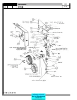
Страница 53: ...FORM NO 56042480 6150 IC 18 06 5 SIDE BROOM LIFT SYSTEM 07 10 ...
Страница 55: ...FORM NO 56042480 6150 IC 20 06 5 SIDE BROOM LEVER 07 3 H50 H54 H35 H46 H54 H85 H113 H52 C 1218 ...
Страница 57: ...FORM NO 56042480 6150 IC 22 06 5 BROOM CHAMBER FLAPS SEALS 07 10 ...
Страница 59: ...FORM NO 56042480 6150 IC 24 06 5 BRAKE PEDAL 80805 1 6 05 07 3 ...
Страница 63: ...FORM NO 56042480 6150 IC 28 06 5 SEAT FLOOR ASSEMBLY 07 10 ...
Страница 71: ...FORM NO 56042480 6150 IC 36 06 5 CONTROL RELIEF VALVE 3 CYL KUBOTA GAS DIESEL 07 3 ...
Страница 73: ...FORM NO 56042480 6150 IC 38 06 5 FWD REV CONTROL 2 CYL KAWASAKI GAS 07 10 ...
Страница 75: ...FORM NO 56042480 6150 IC 40 06 5 FW REV CONTROL 3 CYL KUBOTA GAS DIESEL 07 3 ...
Страница 79: ...FORM NO 56042480 6150 IC 44 06 5 C1222A2 TORQUE HOSE CLAMPS 21 25 FT LBS RESERVOIR 3 CYL KUBOTA GAS DIESEL ...
Страница 81: ...FORM NO 56042480 6150 IC 46 06 5 FUEL TANK GAS 07 10 ...
Страница 83: ...FORM NO 56042480 6150 IC 48 06 5 FUEL TANK DIESEL 07 10 ...
Страница 87: ...FORM NO 56042480 6150 IC 52 06 5 80806 2 2 05 HOPPER COVERS GASKET ASSEMBLY ...
Страница 91: ...FORM NO 56042480 6150 IC 56 06 5 H26 H80 H86 H26 H98 H22 C 1207 9701 DUMP DOOR ...
Страница 97: ...FORM NO 56042480 6150 IC 62 06 5 HYDRAULIC PUMP 3 CYL KUBOTA GAS DIESEL 07 3 80851 SHT01 ...
Страница 99: ...FORM NO 56042480 6150 IC 64 06 5 ENGINE COVER 30 25 32 31 80813 0 3 07 ...
Страница 101: ...FORM NO 56042480 6150 IC 66 06 5 80841 8 05 ACCESS COVER ASSEMBLY ...
Страница 105: ...FORM NO 56042480 6150 IC 70 06 5 ENGINE 3 CYL KUBOTA GAS 07 10 ...
Страница 107: ...FORM NO 56042480 6150 IC 72 06 5 ENGINE 3 CYL KUBOTA DIESEL 07 10 ...
Страница 109: ...FORM NO 56042480 6150 IC 74 06 5 ENGINE 3 CYL DUAL FUEL LP 07 10 ...
Страница 113: ...FORM NO 56042480 6150 IC 78 06 5 80839revF 8 05 HYDRAULIC HOSE DIAGRAM 2 CYL ...
Страница 125: ...FORM NO 56042480 6150 IC 90 06 5 DECALS 08 7 ...
Страница 127: ...FORM NO 56042480 6150 IC 92 06 5 DECALS continued 07 10 ...
Страница 129: ...FORM NO 56042480 6150 IC 94 06 5 C1335 7 04 2 CYLINDER LP CE MODELS ONLY ...
Страница 136: ...101 FORM NO 56042480 6150 IC 06 5 HYDRAULIC SCHEMATIC 2 CYL GAS LP DIESEL 08 7 ...
Страница 138: ...103 FORM NO 56042480 6150 IC 06 5 HYDRAULIC SCHEMATIC 3 CYL KUBOTA GAS DIESEL ...