Always
O
n UPS Systems
M0704_NX_Series_Service_Manual V2.17 2012-06-12
77
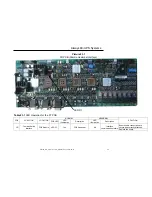
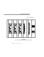
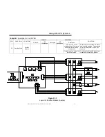
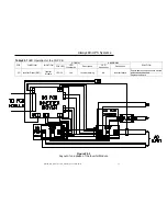
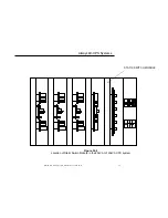
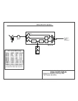
Table 30.1
LED Operation for the 3P PCB
PCB FUNCTION LOCATION
NORMAL ABNORMAL
SOLUTION
PCB
LED
LED
Illumination
Description
LED
Illumination
Description
3P
Static Switch Driver
(R,S,T)
Static Switch
Module
LED P1
Yes
Inverter output is within
normal parameters
No
Inverter operating, transfer
from inverter has failed
Replace the board
LED P2
Yes
Reserve output is within
normal parameters
No
Inverter operating, transfer
from reserve has failed
Replace the board
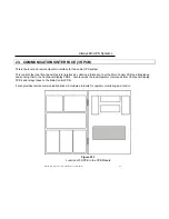
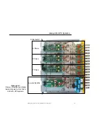
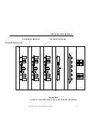
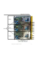
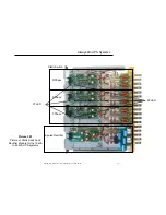
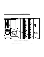
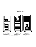
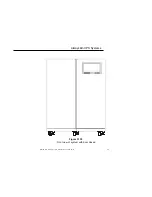
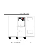
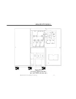
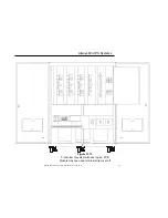
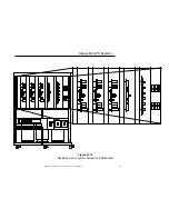
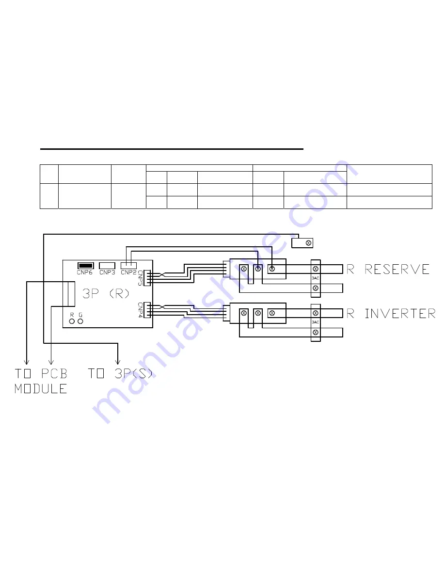
Figure 30.3
Layout of one phase of the Static Switch Module


