
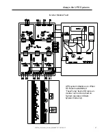
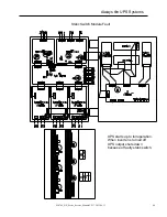
Always
O
n UPS Systems
M0704_NX_Series_Service_Manual V2.17 2012-06-12
36
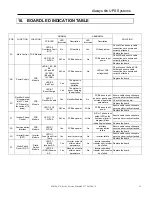
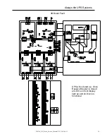
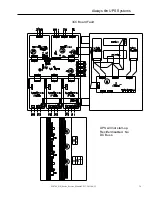
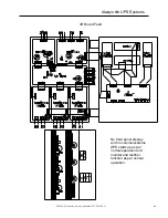
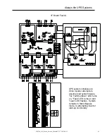
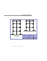
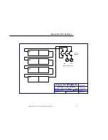
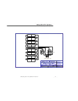
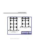
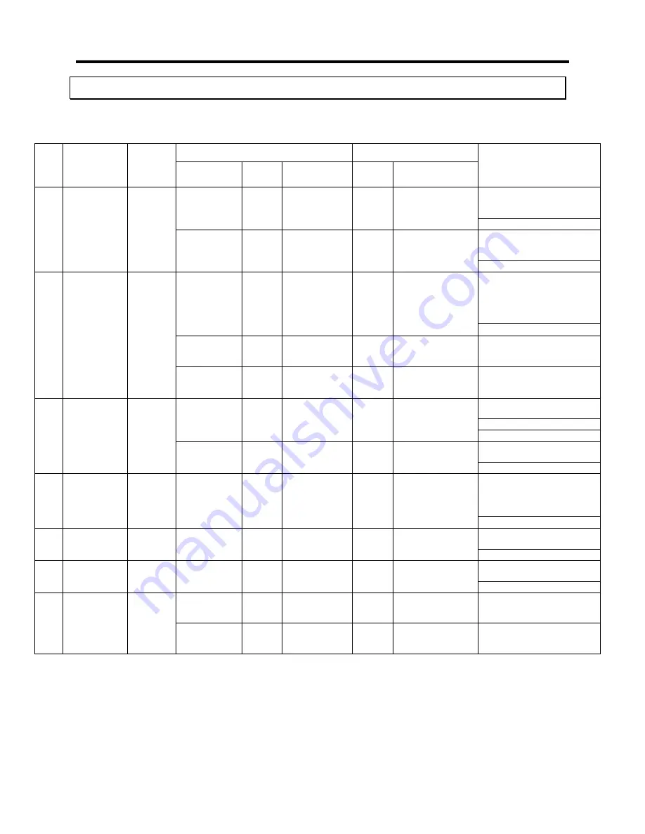
16. BOARD LED INDICATION TABLE
PCB FUNCTION LOCATION
NORMAL ABNORMAL
SOLUTION
PCB LED
LED
Illuminated
Description
LED
Illuminated
Description
3A
Main Control PCB Module
LED A5
Overtemp Fault
(OTF)
No
3G working
Yes
3G has problem
Check 3G and ensure cable
connections are secure and
correctly attached.
Replace the board
LED A1, A2
12VDCA
All Yes
PCB has power
No
PCB has no input
power
Check 3B and ensure cable
connections are secure and
correctly attached.
Replace the board
3B Power
Supply
PCB
Module
LED B1, B2, B3,
B4
(B1 and B3
16VDCA)
(B2 and B4
16VDCB)
All Yes
PCB has power
No
LED's of PCB
extinguished
Check fuse set behind PCB
holder and ensure cable
connections are secure and
correctly attached.
Replace the board
LED B6
Batt Test
Yes
The system is
testing the
batteries
LED B7
Boost Charge
Yes
The system is
boost charging
the batteries.
3C
Rectifier Control
(It is separated
into 3CC and
3CD board for
the option of 12
pulse)
PCB
Module
LED C1
Rectifier Enable
Yes Rectifier
Enabled
No
PCB has no input
power or input power
outside of operating
parameters
Ensure cable connections are
secure and correctly attached.
Check the input power
Replace the board
LED C2, C3
12VDC
All Yes
PCB has power
All No
PCB has no input
power
Ensure cable connections are
secure and correctly attached.
Replace the board
3T
Inverter Phase
Control
PCB
Module
LED T1, T2
12VDCA
All Yes
PCB has power
All No
R, S or T phase lost,
output LED on the
front panel (mimic
diagram) blinks
indicating lost phase.
Ensure cable connections are
secure and correctly attached.
Replace the board
3R
Communication
Interface
PCB
Module
LED R1
5VDCB
Yes
PCB has power
No
Interface
communication
failure
Ensure cable connections are
secure and correctly attached.
Replace the board
3G
Inverter Driver
(RST)
Inverter
Module
LED G1
Fuse Open Over
Temp
Yes Inverter
working No
Inverter
failure
Ensure cable connections are
secure and correctly attached.
Replace the board
3P
Static Switch
Driver (R,S,T)
Static
Switch
Module
LED P1
(RED)
Inverter S.S.
Yes
Inverter output is
within normal
parameters
No
Inverter operating,
transfer from inverter
has failed
Replace the board
LED P2
(GRN) Reserve
S.S.
Yes
Reserve output is
within normal
parameters
No
Inverter operating,
transfer from reserve
has failed
Replace the board


