Always
O
n UPS Systems
M0704_NX_Series_Service_Manual V2.17 2012-06-12
5
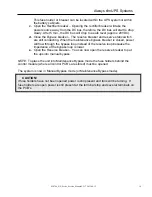
5. RECTIFIER
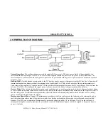
The main function of a rectifier is to convert the AC input power to DC power. The DC
power is then used to charge the batteries, supply the DC bus, which in turn supplies
the inverter.
The rectifier design used in the 10kVA to 60kVA UPS’s include a 6-pulse full controlled
rectifier. Power Factor Correction (PFC) has been added to maintain a high input power
factor, independent of the load power factor. This 6 pulse rectifier smoothes the current
waveform and reduces the harmonic content reflected back to the utility. The control
circuit regulates the DC bus to within 1% of the nominal voltage. Soft walk-in circuitry
(approximately 20 seconds) and current limiting circuitry are used to prevent over
current or surge currents from affecting any part of the UPS system.
Additionally, over and under-voltage protection is added to improve reliability and to
shutdown the rectifier in the event of abnormal conditions. The DC bus is adjustable to
allow for different types and capacities of batteries. The power components used within
the rectifier are specially designed and selected to handle extreme ranges of high
voltage and high current (–25% to +25%).
In order to further improve the power factor and reduce harmonic current drawn by the
rectifier, Always
O
n UPS’s above 80kVA incorporate a 12-pulse full controlled rectifier
(also available as an option on the 10 to 60kVA UPS’s) to reduce the total harmonic
current to less than 12%. A phase shift transformer is added with input inductors to
achieve this higher level of performance while maintaining our high input power factor.
An optional 5
th
harmonic filter can be added to further reduce the total harmonic
distortion current to less than 9%.
The total harmonic current can be decreased to less than 7% with the inclusion of the
18-pulse full controlled rectifier. This option is recommended for the larger (80kVA and
up) UPS systems.
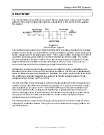
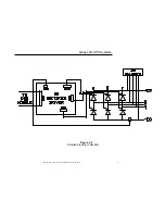
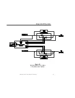
Figure 5.1
Rectifier Block Diagram


