
Always
O
n UPS Systems
M0704_NX_Series_Service_Manual V2.17 2012-06-12
20
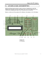
The front panel is located behind the glass window on the front door. It displays the real
time information, UPS Status, battery system and provides the user interface for
controlling and setting the UPS operating parameters. This panel is user friendly. Each
part of the panel is explained below:
A: LCD display-
Real time status, data and historical events are displayed on the LCD.
The UPS parameters, real time clock, inverter, and buzzer can also be
set through this LCD. The LCD is back lit by LED’s for a sharper
display, but in order to lengthen the LED’s life time, the LED will
automatically shut off 3 minutes after a key has been pressed, and will
light up again when one of the up/down/enter keys are pushed.
B: Warning LED’s-
When an abnormal condition occurs, these LED’s will illuminate
allowing the user to identify the cause of the fault. This will also allow
the service personnel the ability to initially troubleshoot the system.
These LED’s are described below:
•
RECT AC FAIL –
supply to the
rectifier is outside of the operating
window. This is related to the supply voltage out of range, the phase
rotation is incorrect or the rectifier has been shutdown (refer to
C:
Status LED’s
).
•
RESERVE FAIL –
supply to the
reserve is outside of the operating
window. This is related to the supply voltage out of range or frequency
out of range (refer to
C: Status LED’s
).
•
FUSE/TEMP –
inverter has shutdown due to inverter fuse open or heat
sink temperature above operating parameters.
•
OVERLOAD –
an overload condition has occurred on the output.
•
HIGH DC –
the DC voltage has exceeded maximum operating level
(over 430VDC). The bus voltage is limited to this voltage.
•
BAT LOW –
this LED will be lit as long as the DC voltage is lower than
320VDC.
•
BAT LOW STOP –
the LED will be lit as long as the DC voltage is
lower than 295VDC. The inverter will not activate until the DC voltage
is above this level.
•
FAULT –
the inverter has shutdown because an abnormal condition
has occurred. Possible conditions include overload, short circuit, high
DC shutdown, fuse/over temperature, bypass breaker on or
emergency stop (refer to
C: Status LED’s
).
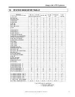
C: Status LED’s-
24 LED’s represent the real-time information about the status of the
UPS system. These LED’s will aid in diagnosing and trouble shooting
abnormal conditions. The 24 LED’s represent the following:
•
INVERTER ON –
inverter is running.


