
Always
O
n UPS Systems
M0704_NX_Series_Service_Manual V2.17 2012-06-12
16
-
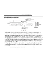
Status LEDs indicate status of sub-systems – many alarm indicators will
be illuminated as the rectifier does not yet have AC power applied, and the
DC buss has not been established;
Battery Low Stop, low battery, fuse/temp, Rectifier AC Fail,
Rotation Error
c.
Push the OFF button (0) on front panel to clear alarm indicators on the Main
Control PCB.
d.
Open the Bypass breaker.
e.
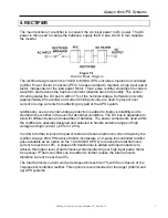
Turn Rectifier Breaker to ON position
-
Power is applied to the rectifier control module and rectifier power devices.
Once the power has been qualified as acceptable, the rectifier will start to
ramp up the DC voltage from 0Vdc to 390Vdc over a period of
approximately 20 seconds. The DC buss generated is used to
simultaneously charge the batteries and supply DC to the inverter.
-
Fault indicators will clear sequentially as the DC voltage rises to normal
operating levels;
Rectifier AC Fail, Rotation Error, Fuse/temp, Battery Low, Battery
Low Stop
f.
Turn Battery fuse or Breaker to ON position.
-
Connects the battery bank to the DC buss being generated by the rectifier.
g.
Turn Inverter ON – push buttons on front panel.
-
Inverter will ramp up over a 7 second period and then supply power to the
output of the UPS.
-
Fans will start, output voltage will be present.
-
Indicators will show normal inverter operation of the system.
h.
Turn Inverter Off – push buttons on front panel.
-
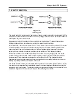
This will turn the inverter OFF and put the UPS in Static bypass mode.
Reserve power will feed the output of the UPS. The switch from inverter to
reserve power should be seamless and uninterrupted.
-
Indicators will show Static Bypass status.
i.
Turn Inverter ON – push buttons on front panel.
-
Inverter will ramp up for 7 seconds then Static switches will transfer to
Inverter mode. The switch from reserve power to inverter should be
seamless and uninterrupted.
-
Indicators will show normal inverter operation of the system.
j.
Backup Mode test – turn Input Breaker to OFF position.
-
Utility power will be removed from the UPS inputs.
-
Rectifier will become disabled and the Batteries will be providing DC
power to the Inverter. The switch to backup mode should be seamless and
uninterrupted.
-
Indicators will show backup mode operation, UPS will be beeping.
Rectifier AC Fail, Rotation Error, Reserve AC Fail, Reserve Freq
Fail
k.
Rectifier restart – Turn Input breaker to ON position.


