

Always
O
n UPS Systems
M0704_NX_Series_Service_Manual V2.17 2012-06-12
27
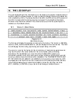
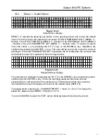
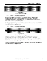
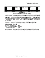
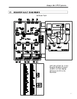
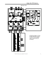
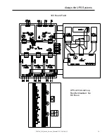
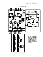
Listed below are all the fault conditions that can be displayed:
1
st
row: HIGH DC SHUTDOWN
– DC Bus voltage out of operating range.
2
nd
row: SHORT CIRCUIT!
– a short circuit condition has occurred on the output.
FUSE/OVERHEAT
–
a fuse has blown or the system has shutdown due to
overheating.
OVERLOAD SHUTDOWN
– system has exceeded the overload limit beyond the
operating window.
EMERGENCY STOP –
user has activated the emergency stop feature.
INVERTER ABNORMAL –
inverter is not operating within specified parameters.
3
rd
row: BYPASS ON SHUTDOWN
– inverter failure, system operating in bypass mode.
The UP (
↑
) or DOWN (
↓
) key has no function in this menu. The screen will go back to
MENU 1, when ENTER(
↵
) is pressed.
14.4.
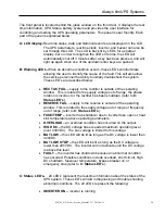
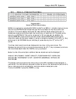
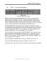
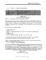
Menu 3 – Real Time Data Menu
MENU 3 is reached by selecting REAL TIME DATA on MENU 1. The cursor(
→
) is used to
select what type of real time data the user would like to view, RECTIFIER DATA (MENU 6
– Section 10.7), RESERVE DATA (MENU 7 – Section 10.8), OUTPUT DATA (MENU 8 –
Section 10.9) and OTHER DATA (MENU 9 – Section 10.10). To select one of the different
menu options move the cursor(
→
) until it is pointing at the correct selection, by press the
UP (
↑
) key or the DOWN (
↓
) key. To confirm and select the menu option press the ENTER
(
↵
) key.
Selecting the ‘EXIT’ option (blinking instead of pointed by cursor) will return you to MENU
1.
R E A L
T I M E D A T A
R E C T I F I E R
D A T A
O T H E R
D A T A
R E S E R V E
D A T A
O U T P U T D A T A
E X I T
Figure 14.4.1
Real Time Data Menu


