27
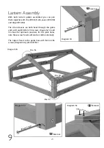
Lantern Assembly
9
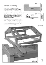
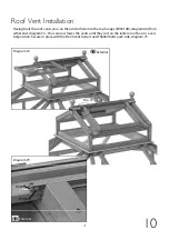
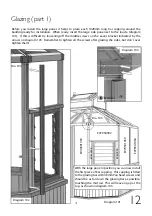
Diagram 61
Diagram 62
External
Section
EV1007
CEDAR CAPPING
Glazing
Rubber
EV1103M
Section
ALUMINIUM
CAPPING
Dia. 62
EV
11
07
/ E
V1
10
3M
EV
11
07
/ E
V1
10
3M
EV
11
07
/ E
V1
10
3M
EV
11
07
/ E
V1
10
3M
D
72
9T
G
40mm CSK Screw
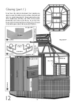
Having turned the lantern the right way up
you need to add its upper panes (D729TG).
The lantern roof glass is held in place by 1
glass stop (EV0313) per pane and secured with
capping on each side using 40mm pan head
screws, diagram 62. If you have the optional
aluminium bar capping you need to insert the
rubber into the rubber channels and trim it to
length prior to attachment.
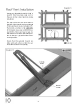
Important:
Please make sure that you use the
40mm countersunk (EV0338) screws where
the vent/s will be located (two each side), the
usual pan headed (EV0332) screws will pre-
vent the vents from closing properly.
EV
03
13

