Stratix II Memory Board 2 Rev A User Guide Rev 0.1
Altera Confidential
17
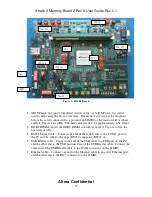
2. Set the switches (MPGM pins) on S1 to the correct values for this test, as shown in
Table 2.
3. Move the power switch to the ON position.
4. Press the SYS_RESETn (S3) pushbutton to reload the FPGA.
5. Confirm that the Stratix II device has finished configuration (the CONF_DONEn LED
(D12) illuminates). The Error LED (D17) will illuminate if there is an error.
2.3.5.2
Run the QDRII SRAM Device(s) Test
Perform the following steps to execute the QDRII SRAM Device(s) test.
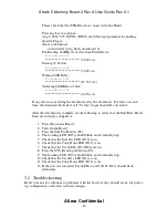
1. Press the PB3 (S8) pushbutton to reset and run the design.
2. Confirm that LED0 and LED1 are on, and that LED4 and LED5 are blinking. If so, the
test is a success. LED0 turns on to indicate that the test is not failing. LED1 turns on to
indicate that the test is complete.
3
Diagnostic Tests
The diagnostic tests that follow are for execution of the individual batch files using
the pc to load the files through the JTAG port onto the Stratix II.
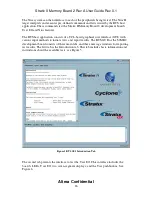
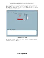
The User IO and NIOS stamp functions are exercised using a prototype of the Board
Test System (BTS). This design is the “safe” image that is loaded by pressing the
SAFE button (S2). This loads a NIOS based system design that will communicate
with the host using a RS232 link. The user interface is TCL based. The GUI has
several “pages” for the various features that are tested.
The memory tests are hardware based at this point and are stored as pages in the on-
board flash memory. These are loaded by setting the MPGM DIP switch settings
then pressing SYS_RESETn pushbutton (S3). The memory tests consist of a state
machine that writes PRBS data to the memory device at max speed then reads back
the data and compares it to an expected value. If an error is detected, LED0 (D26)
will turn off indicating a failure. The data is written to the full address range of the
device before it is read back. Each time the full write then read cycle is completed, it
is considered one test. The designs keep track of when the test has completed. Once
completed LED1 (D25) lights up. The DDR2 designs run a infinite number of times
and will not stop unless board is shut down or another memory test is run.
3.1
Set up S2MB2 for Individual Diagnostic Tests


