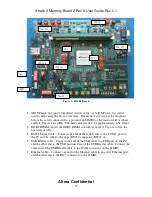
Stratix II Memory Board 2 Rev A User Guide Rev 0.1
Altera Confidential
10
1
DDR2 SDRAM DIMM Interface
2
DDR2 SDRAM Devices Interface
3
QDRII SRAM Device(s) Interface
4
10/100 Ethernet interface
5
MAX®/MAX II device
6
General purpose interface (user pushbuttons, dipswitches, LEDs, and
displays)
7
RS-232 interface
8
JTAG interface
9
Stratix II configuration settings interface
10
Clock source (crystal oscillators and clock input and output)
11
Stratix II active serial interface
12
Tektronix high-speed differential debug interface
13
Agilent high-speed differential debug interface
14
Stratix II device
15
Power connectors and circuitry
16
Flash Memory device
17
SRAM devices
Table 1 S2MB2 Interfaces
2.3
Run the Preloaded Diagnostic Tests
Each interface on the S2MB2 board has an associated diagnostic test that exercises
the interface at the supported I/O rates. Although the tests are not exhaustive, they
help you confirm that each interface runs according to its intended design. A subset of
the diagnostic tests are loaded into the Stratix II Memory Board 2’s Flash memory. If
the S2MB2 does have preloaded diagnostic tests already in Flash, then at power up
the MAX® or MAX II device checks the MPGM value and uses the Flash memory to
configure the Stratix II device with the desired configuration image. This chapter
describes how to set up and perform these preloaded diagnostic tests, including:
User I/O and Nios® Stamp
DDR2 SDRAM dual interface memory module (DIMM)
DDR2 SDRAM devices
QDRII SRAM device(s)
The following sections describe how to perform each test, including the equipment
you need to perform each test, how to set up the board, and the test procedure. Table
2 shows the switch settings you must make to load the designs on power up. If the
Flash is blank or corrupted, there are instructions on how to program the Flash in
“Downloading Factory Image”, Section 3.1.9.
For more details on these designs, refer to Section 3.3, Diagnostic Test Details.


