Allen-Bradley Kinetix 5500 Скачать руководство пользователя страница 447

CIP Axis Attributes 

Chapter 4 


Rockwell Automation Publication MOTION-RM003I-EN-P - February 2018 

447


1.


Switch to Stopping state. 

2.


Apply "Current Decel" or "Ramp Decel" method to stop motor. 

3.


Wait for zero speed or 'Stopping Time Limit' or a factory set timeout, 

whichever occurs first. 

4.


Deactivate Mechanical Brake output to engage brake. 

5.


Wait for "Mechanical Brake Engage Delay" while brake engages. 

6.


Perform (optional) Brake Proving operation to verify brake control of load. 

7.


Disable inverter power structure. 

8.


Transition to Stopped state. 

9.


Deactivate Resistive Brake contactor to disconnect motor from inverter 
power structure. 

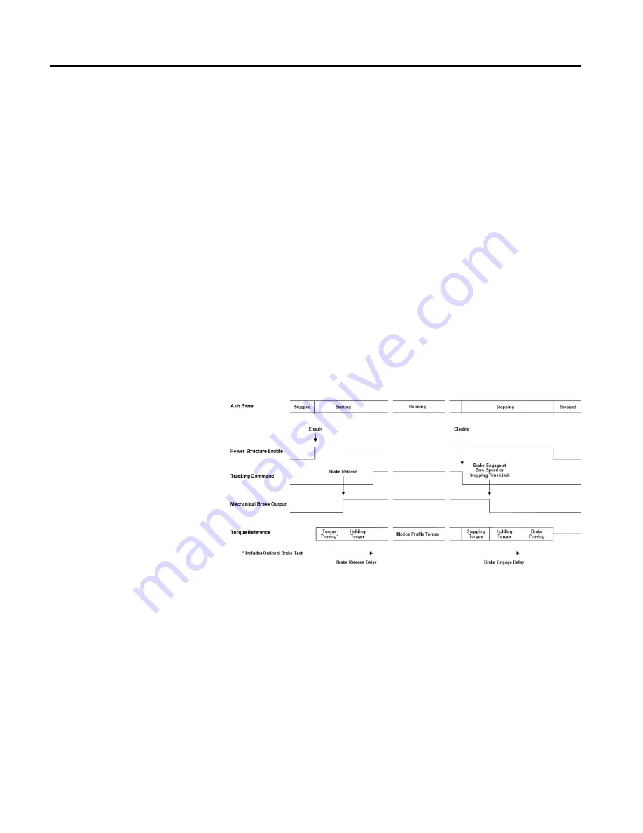
The following diagram illustrates a Category 1 Stop Sequence: 


Category 2 Stop Sequence 

Torque is applied to stop the motor and inverter is left enabled to provide holding 
torque. The mechanical brake is not used. Brake Proving is not applicable. A 

Category 2 Stop is only allowed in no Start Inhibit condition is present. 

1.


Switch to Stopping state. 

2.


Apply "Current Decel" or "Ramp Decel" method to stop motor. 

3.


Wait for zero speed or "Stopping Time Limit" or a factory set timeout, 

whichever occurs first. 

Содержание Kinetix 5500

Страница 1: ...Reference Manual Integrated Motion on the EtherNet IP Network ControlLogix CompactLogix Kinetix 350 Kinetix 5500 Kinetix 5700 Kinetix 6500 PowerFlex 527 PowerFlex 755 ...

Страница 2: ...he contents of this manual in whole or in part without written permission of Rockwell Automation Inc is prohibited Throughout this manual when necessary we use notes to make you aware of safety considerations WARNING Identifiesinformationaboutpractices orcircumstancesthat cancause an explosionina hazardousenvironment which may leadto personal injury ordeath property damage or economic loss ATTENTI...

Страница 3: ... Subject Reason Organizationbyfunctional category Updatedthroughouttoalignwiththeonline help AccessRule naming conventions Updatedthroughoutto reflect changes made inthis versionof Logix Designerapplication New or enhanced features This table contains a list of topics changed in this version the reason for the change and a link to the topic that contains the changed information Topic Name Reason S...

Страница 4: ...de Fault andAlarmAttributesonpage297 MotionControl ConfigurationAttributesonpage 317 MotionPlannerConfigurationAttributesonpage 367 PositionLoopAttributesonpage 206 Powerand Thermal Management Status Attributesonpage 254 Torque Force Control ConfigurationAttributes onpage211 VelocityLoopAttributesonpage228 VelocityLoop ConfigurationAttributesonpage221 Updatedminimum maximum and default values CIP ...

Страница 5: ...28 Command Data Sources 29 Command Fine Interpolation 30 Command Ramp Generator 33 Feedforward Signal Selection 34 Command Notch Filter 35 Current Control Behavior 35 Current Vector Limiter 36 Voltage Output 37 Current Feedback 37 Motor Commutation 38 Event Capture Behavior 38 Event Input Sources 39 Event Latches 40 Event Time Stamps 40 Fault and Alarm Behavior 41 Exceptions 41 Absolute Position R...

Страница 6: ... Attribute Units 90 CIP Data Types 91 Device Function Codes 91 Required vs Optional Axis Attributes 93 Identify Motion Axis Attributes Based on Device Function Codes 95 Attribute Conversion from SERCOS to Integrated Motion on the Ethernet IP Network 111 Drive Supported Optional Attributes 114 Kinetix 350 Drive Module Optional Attributes 116 Kinetix 5500 Hardwired STO Drive Module Optional Attribut...

Страница 7: ...al Attributes 235 CIP Axis Status Attributes 236 Event Capture Attributes 247 Drive Attributes 249 Drive General Purpose I O Attributes 249 Drive Output Attributes 251 Power and Thermal Management Configuration Attributes 252 Power and Thermal Management Status Attributes 254 Drive Commissioning and Tuning Attributes 257 Auto Tune Configuration Attributes 258 Hookup Test Configuration Attributes 2...

Страница 8: ...mples 386 Motor Attributes 388 General Linear Motor Attributes 388 General Motor Attributes 389 General Permanent Magnet Motor Attributes 396 General Rotary Motor Attributes 399 Induction Motor Attributes 401 Linear PM Motor Attributes 404 Interior Permanent Magnet Motor Attributes 406 Load Transmission and Actuator Attributes 409 Rotary PM Motor Attributes 412 Safety Attributes 414 Axis Safety St...

Страница 9: ...I EN P February 2018 9 Chapter 5 Module Configuration Block Attributes 471 Module Class Attributes 473 Module Axis Attributes 474 Module Feedback Port Attributes 489 Module Timing Attributes 490 Module Support Attributes 492 Module Configuration Attributes Index ...

Страница 10: ......

Страница 11: ...nual publication2094 RM001 Provides informationonwiring configuring and troubleshooting the safe speed features of yourKinetix 6200and Kinetix 6500 drives Kinetix6200and Kinetix 6500Safe Torque Off Safety ReferenceManual publication2094 RM002 Provides informationonwiring configuring and troubleshooting the safetorque off features of yourKinetix 6200and Kinetix 6500 drives Kinetix5500Servo DrivesUs...

Страница 12: ...ODVA specifications ODVA is theorganizationthat supports network technologiesthatare builtonthe CommonIndustrial Protocol CIP DeviceNet EtherNet IP CompoNet and ControlNet You can view or download publications at http www rockwellautomation com literature To order paper copies of technical documentation contact your local Rockwell Automation distributor or sales representative Copyright Notice Cop...

Страница 13: ...ryTalk Services Platform FactoryTalk View FactoryTalk View SE FLEX Ex FlexLogix FLEX I O Guard I O High Performance Drive Integrated Architecture Kinetix Logix5000 Logix 5000 Logix5550 MicroLogix DeviceNet EtherNet IP PLC 2 PLC 3 PLC 5 PanelBuilder PowerFlex PhaseManager POINT I O PowerFlex Rockwell Automation RSBizWare Rockwell Software RSEmulate Historian RSFieldbus RSLinx RSLogix RSNetWorx for ...

Страница 14: ...ncy during installation operation or maintenance This product s implementation may vary among users This document is current as of the time of release of the product however the accompanying software may have changed since the release Rockwell Automation Inc reserves the right to change any information contained in this document or the software at any time without prior notice It is your responsib...

Страница 15: ...ams provided in Behavior models used in CIP Motion on page 25 The Control Modes table lists the Motion Axis Attributes specific to the CIP Drive data type The table identifies the attribute implementation rule as either Required Optional or Conditional Drive replicated attributes are identified also Review the Interpret the Attribute Tables on page 87 section for an explanation of how the data for...

Страница 16: ...ion Instruction Compatibility on page 22 Device Function Codes on page 91 Identify Motion Axis Attributes Based on Device Function Codes on page 95 Motion control modes are organized around the general philosophy that position control is the highest form of dynamic control That is position control implies velocity control and velocity control implies acceleration control Acceleration is related to...

Страница 17: ... applications by substituting the terms force for torque and mass for inertia With that understanding we use torque rather than force in the control mode diagrams without loss of generality See also Position Control Mode on page 17 Velocity Control Mode on page 18 Torque Control Mode on page 20 No Control Mode on page 21 In Position Control application mode either the application control program c...

Страница 18: ...rive A feedback device for this configuration is generally required to achieve good positioning accuracy The feedback device can also be used to return Actual Velocity and Actual Acceleration data to the controller using the cyclic data connection In addition to Command Position the controller can pass Command Velocity and Command Acceleration for the purposes of forward control See also Control M...

Страница 19: ...included it may be used to return actual position velocity and acceleration data to the controller using the cyclic data connection When the feedback device is not included only estimated velocity can typically be returned to the controller In addition to Command Velocity the controller can also pass Command Acceleration for the purposes of forward control Acceleration Control Method While not a m...

Страница 20: ...nnection See also Control Modes on page 16 In Torque Control application mode the application control program or the motion planner provide torque setpoint values to the device using the cyclic data connection Because motor current and motor torque are generally related by a torque constant Kt torque control is often synonymous with current control A position feedback device for this control mode ...

Страница 21: ...trated in the following diagram No Control Feedback Only No Control mode also applies to other CIP Motion device types such as standalone Bus Power Converters and dedicated Motion I O device types Since there is no feedback channel that is associated with these device types no actual position is returned to the controller See also Control Modes on page 16 Within this basic control paradigm there i...

Страница 22: ...ble Frequency Drives VFDs orso calledVolts Hertz drives 2 R C PI VectorControl PI VectorControl isa closed loop controlmethod that uses actual orestimatedfeedbackforclosed loop cascaded PIcontrolofmotordynamics that is position velocity acceleration and torque and alwaysincludes independent closed loopPI controlofIq andId componentsof themotorcurrent vector 3 127 Reserved 128 255 VendorSpecific Ax...

Страница 23: ...op Feedback Vel Loop NoFeedback Torque Loop State Control MotionDirect Drive On MDO MotionDirect Drive Off MDF MotionServoOn MSO x MotionServoOff MSF x x x x x MotionAxis FaultReset MAFR x x x x x x MotionAxis Shutdown MASD x x x x x x MotionAxis ShutdownReset MASR x x x x x x MotionDrive Start MDS Event Control MotionArmWatchPosition MAW x x x x MotionDisarm WatchPosition MDW x x x x MotionArmReg...

Страница 24: ...wnReset MCSR x x x x x x MotionCoordinatedChange Dynamics MCCD c x c c MotionCoordinatedTransform MCT c x c c MotionCalculate Target Position MCTP x c x c c x MotionMasterDrivenCoordinated Control MDCC c x c c MotionConfiguration MotionRunAxis Tuning MRAT x x x MotionApplyAxis Tuning MAAT MotionRunHookup Diagnostic MRHD x x x x x x MotionApplyHookup Diagnostic MAHD Group Control MotionGroupStrobe ...

Страница 25: ...locity Control Behavioronpage 79 MotionControl Axis BehaviorModelonpage51 See also Standard Exceptions on page 456 Interpret the Attribute Tables on page 87 While dynamic motor control through an acceleration command is not common in the industry Acceleration Control completes the dynamic progression from Velocity Control to Torque Control The output of the velocity loop Velocity Loop Output also ...

Страница 26: ...bserver on page 27 The output of the acceleration command summing junction signal passes through a limiter to produce the Acceleration Reference signal The Accel Limiter applies a directional acceleration limit either the Acceleration Limit or the Deceleration Limit to the input command signal based on the sign of the signal The following diagram illustrates this process See also Load Observer on ...

Страница 27: ... Feedback 1 or Feedback 2 Which feedback source is used by the loop is governed by the Feedback Mode In general the Load Observer works best when by using a high resolution feedback device Acceleration and Torque Estimates The output of the Load Observer is the Acceleration Estimate signal that is subsequently applied to the acceleration reference summing junction When configured for Load Observer...

Страница 28: ...e Load Observer s estimated velocity signal can be applied as feedback to the velocity loop by selecting Load Observer with Velocity Estimate or Velocity Estimate Only Selecting Acceleration Feedback degenerates the Load Observer to an acceleration feedback loop by disconnecting the Acceleration Reference input from the observer The observer s velocity estimate is not available in this mode of ope...

Страница 29: ...based Motion Planner using the CIP Motion C to D Connection In this context command data can take the form of Controller Position Velocity Acceleration and Torque Commands generated by the Motion Planner The command data elements provided are specified by the Command Data Set attribute which is based on the selected Control Mode The primary command data element can be augmented by higher order com...

Страница 30: ...28 For synchronized high performance applications using CIP Motion command data is received from the CIP Motion C to D Connection or the device s local Motion Planner and based on the connection s Command Target Update element being set to Interpolate processed by the Fine Interpolator functionality of the Command Generator The job of the Fine Interpolator is to compute coefficients to a trajector...

Страница 31: ...er update corresponding to Command Target Time t1 the position velocity acceleration and torque command values are the values sent in the latest Motion Planner update for example P0 V0 A0 and T0 P t1 P0 V t1 V0 A t1 A0 T t1 T0 Using the above polynomial interpolation equations the CIP Motion device can compute position velocity acceleration and torque command values at any time by plugging in the ...

Страница 32: ...nthe following nomenclature T ControllerUpdate Period P0 P0 P 1 V0 V0 V 1 P0 2P 1 P 2 A0 A0 A 1 V0 2V 1 V 2 P0 3P 1 3P 2 P 3 The preceding polynomial coefficients should be applied to the fine interpolator as soon possible after t is equal to or greater than t0 Applying the new coefficients too early for example with significantly less than t0 can create unnecessary error in the command trajectory...

Страница 33: ...be applied to the control structures of Variable Frequency drives without interpolation or extrapolation See also Command Generation Behavior on page 28 When operating in Closed Loop Velocity mode the Ramp Generator feature of the Velocity Fine Command Generator block is applied to the Controller Velocity Command value sent by the controller when the Command Target Update element of the connection...

Страница 34: ...lows three separate Skip Speeds to be defined that shift the Velocity Command signal to avoid or skip these problematic speeds The Skip Speed Band determines the range of speeds centered on the three Skip Speeds that the device avoids If the Velocity Command is within the Skip Band but below the Skip Speed the Velocity Command output is set to the Skip Speed minus half the Skip Speed Band If the F...

Страница 35: ...nd magnitude of the motor stator current vector with respect to the rotor magnetic flux vector The Current control loop is responsible for providing this control and is actually composed of two PI loops one that controls the torque producing current Iq and one that controls the flux producing current Id It is the quadrature component of current Iq that is used for dynamic Torque Control In the cas...

Страница 36: ...ference signal This limiter computes the combined vector magnitude of the Iq Current Reference and the Id Current Reference signals The resultant current vector magnitude is compared to the Operative Current Limit that represents the minimum current limit from among a set of potential current limits of the drive device and motor If the vector magnitude exceeds the Operative Current Limit the Iq Cu...

Страница 37: ...ctor transformation block to transform the torque producing Vq and flux producing Vd command signals from the rotating synchronous reference frame to the stationary stator reference frame The resultant U V and W Output Voltage values are then applied to the motor by Pulse Width Modulation PWM The PWM Frequency is also a configurable attribute The magnitude of the Vq Vd vector is calculated in real...

Страница 38: ...the feedback device is calibrated to the absolute orientation of the rotor by using the Commutation Offset attribute the commutation block can then generate the true Electrical Angle of the rotor This signal is used to perform the vector transforms between the rotary and stationary motor frames and can also be used for any other algorithms that require knowledge of rotor position See also Current ...

Страница 39: ...agram provides an overview of the event capture behavior model See also Event Input Sources on page 39 Event Latches on page 40 Event Time Stamps on page 40 The Motion Device Axis Object defines a mechanism to capture both the feedback position and time stamp associated with specific state transitions of Event Input Sources ...

Страница 40: ...h can be any of a number of different combinations of home switch and marker input events for example marker transitions switch transitions or switch transitions followed by a marker transition With hardware based event latches event capture accuracy is in general only limited by the latency of the associated event input Registration and Marker event inputs are lightly filtered so event capture ac...

Страница 41: ...he condition of the motion axis in real time without cumbersome polling The CIP Axis Status attribute contains bits to indicate whether an alarm condition is present The CIP Axis State enumeration indicates when the axis has a major fault which could be a regular runtime CIP Axis Fault Safety Fault or an Initialization Fault The Axis Fault Code and related attributes are used to report the specifi...

Страница 42: ...iguration faults safety faults module faults group faults motion faults or runtime exception conditions that the axis has been configured to regard as a fault Fault conditions can occur in either the controller or motion device If a runtime fault occurs during an operational state for example Running or Testing it will result in the device stopping or aborting all axis motion either automatically ...

Страница 43: ...homing procedure usually requires the machine to be taken offline and placed in a manual operating mode for example not making product anything that would require you to rehome one or more axes on the machine is undesirable This is downtime and costs money The APR feature maintains the machine reference or absolute position through power cycles program downloads and even firmware updates Absolute ...

Страница 44: ...eration on page 45 APR Fault Attributes on page 279 The Absolute Position Recovery is not retained after the following A project is exported saved as a L5K or L5X and imported downloaded A major non recoverable fault MNRF A power loss On a Control Logix 5570 controller without an ESM Tip The APRcanpotentially be restored froma Secure Digital Cardona ControlLogix 5570 Controller if a1756 ESM is not...

Страница 45: ...downloaded to the controller A user program is downloaded A user program and tags are restored from CompactFlash card Manual Restore Power up restore when configured Firmware is updated using ControlFLASH An SSV to change Feedback Polarity or One of the attributes which results in a change to the Motion Resolution attribute See also APR Fault Generation on page 45 APR Fault Attributes on page 279 ...

Страница 46: ...PR fault Changing the axis feedback device or feedback polarity without downloading the project will also generate an immediate APR fault Axis hardware change or malfunction Axis hardware resource insufficiency Hardware resource insufficiencies are only detected during download or ControlFLASH firmware update and will result in an APR fault During axis configuration the following checks are made 1...

Страница 47: ...ecipe change If the Axis Homed status bit is clear indicating that position has not been absolutely referenced to the machine the APR function is bypassed and there is no attempt to restore absolute position See also APR Fault Attributes on page 279 APR Fault Examples on page 47 Scaling Changing the Scaling parameters can potentially generate an APR fault because internal constants computed from t...

Страница 48: ...mptions need to be taken into consideration In each of these cases the APR feature restores absolute position and preserves the state of the Axis Homed bit indicating that the axis has a machine referenced absolute position All relevant axes are CIP axes Yes machine reference is recovered for Axes that have been homed No machine reference is not recovered for Axes that have been homed Scenario Eve...

Страница 49: ...motorcableonanaxis Yes InhibitorUninhibit anaxisordrive Yes Battery Backed Controller Savetoa Secure Digital card 2 witha homed axis and you initiatethe restore Yes RIUP controller Yes Cycle poweroncontroller Yes Cycle poweroncontrollerthat is configured to restoreuserprogramfrom a Secure Digital cardonpowerup Yes RAMmemory becomescorrupt andthe userprogram is restored fromthe Secure Digital card ...

Страница 50: ...d Yes Change drivewithsameordifferent catalog number Yes Change motorbutnotfeedbackdevice Yes Downloadsame programwithno hardware changes Change the name of anaxis Yes Downloadthe same LogixDesignerapplicationprogramtothe controller Yes SaveAswitha different file name Yes Partial Export andthenimportanaxis Yes Addedapplicationlogic Yes Downloadthe LogixDesignerapplicationprojectof ExistingAxis Yes...

Страница 51: ... the controller or motion device during operation Review the diagram for the behavior model to see how the axis state maps to identity object states Active Control Axis Behavior Model on page 52 Feedback Only Axis Behavior Model on page 54 CIP Motion Converter Axis Behavior Model on page 56 Motor Attributes Model on page 57 Fault Reset State Transition Precedence When an axis is in the Major Fault...

Страница 52: ...ate transitions can be initiated either directly using the Axis Control request mechanism or by conditions that occur in either the controller or motion device during operation The following diagram illustrates the basic operating states of the Motion Control Axis when actively controlling axis motion Control Mode No Control Shaded regions show mapping of Axis States to corresponding Identity Obje...

Страница 53: ...arge Bus Up Stopped StartInhibited Shutdown Shutdown StartInhibited MajorFault MajorFaulted StartInhibited Inhibits Cleared Stopped MajorFaulted Shutdown PowerStructure Enabled 1 Aborting MajorFaulted Disable PowerStructure Enabled 1 Aborting MajorFaulted StartInhibit PowerStructure Enabled 1 Aborting MajorFaulted FaultReset Shutdown 1 Shutdown MajorFaulted FaultReset Shutdown 0 DC Bus Up 0 Pre Ch...

Страница 54: ...tdown Stopping Running MajorFault Aborting Running Disable Stopping Any State ConnectionClose Initializing Any State ConnectionLoss MajorFaulted Eventdisablestheaxispowerstructureafter aCategory2Stop leaves the axis in activehold condition See also State Behavior on page 61 Fault and Alarm Behavior on page 41 Exceptions on page 41 Stopping Sequences on page 445 CIP Axis Status Attributes on page 2...

Страница 55: ...ulted Initializing InitializationComplete StartInhibited Shutdown MajorFault MajorFaulted Shutdown ShutdownReset Running StartInhibited Shutdown Shutdown StartInhibited MajorFault MajorFaulted StartInhibited Inhibits Cleared Running MajorFaulted FaultReset Shutdown 1 Shutdown MajorFaulted FaultReset Shutdown 0 StartInhibited 0 StartInhibited MajorFaulted FaultReset Shutdown 0 StartInhibited 0 Runn...

Страница 56: ...tions for the Axis State Model of a CIP Motion Converter axis are explicitly defined in the following table Current State Event Conditions NextState Off PowerUp Self Test Self Test Self Test Complete Initializing Initializing InitializationFault MajorFaulted Initializing InitializationComplete Pre Charge Shutdown MajorFault MajorFaulted Shutdown ShutdownReset Pre Charge StartInhibited Shutdown Shu...

Страница 57: ...ded Required versus Optional is further differentiated by abbreviations for PM Permanent Magnet and IM Induction Motors It is implied that these motor attributes are applicable to all drive modes F P V and T but not applicable for N No Control axis configurations where there is no active motor control function For induction motors the Motion Control Axis leverages the IEEE recommended phase neutra...

Страница 58: ...sion and Actuator Attributes on page 409 Rotary PM Motor Attributes on page 412 In Position Control mode the only operative Control Method supported is Closed Loop servo control When performing closed loop Position Control the device applies the Position Command signal output of the Command Generator to the position loop summing junction In addition to the Position Command a Position Trim input is...

Страница 59: ...xibility allows the position loop to operate with either a motor based feedback device that is typically attached to the Feedback 1 channel or a load side feedback device that is connected to the Feedback 2 channel Which feedback source is used by the loop is governed by the Feedback Mode attribute When the Feedback Mode calls for Dual Feedback operation the position loop utilizes the Feedback 2 c...

Страница 60: ... in high performance motion control applications An alternative approach that has superior dynamic response is to use Velocity Feedforward The Velocity Feedforward feature is used in Position Control mode to provide the bulk of the Velocity Reference input necessary to generate the desired motor velocity It does this by scaling the Fine Velocity Command signal output of the Command Generator by th...

Страница 61: ...ed with the pole of the filter If Kn 1 the filter provides lead compensation If Kn 1 the filter provides lag compensation If Kn 0 the lead lag filter becomes a pure low pass filter If Kn 1 the filter is disabled Finally a notch filter is included that has been shown to be effective in solving certain types mechanical compliance problems The equation for this filter is as follows In this equation Q...

Страница 62: ...IP Motion controller and the associated CIP Motion device the axis state transitions to the Initializing state where CIP Motion connections are created and the devices are configured by the controller From this point on the Axis State value in the controller is influenced by the Axis State value in the device using the CIP Motion connection If the CIP Motion device supports stand alone operation u...

Страница 63: ... configuration process also allows the serial number of the component to be read by the controller to determine if the component has been replaced The controller does not complete the configuration process Configuration Complete until all configuration attributes have been successfully acknowledged If the device supports synchronous operation the controller then synchronizes with the device using ...

Страница 64: ...he Stopped state the device s inverter power structure will either be disabled and free of torque Power Structure Enabled status bit clear or held in a static condition using an active control loop Power Structure Enabled status bit set No motion can be initiated by the device in the Stopped State nor can the device respond to a planner generated command reference Tracking Command status bit clear...

Страница 65: ...for example services that require an active power structure to execute the axis immediately transitions to the Starting State Power Structure Enabled status bit set and then once the Starting conditions are met the axis transitions to the Testing state This Testing state is like the Running state in that the device s power structure is active but in the Testing state one of the device s built in t...

Страница 66: ...cted Stopping Action procedure has completed the axis transitions to the Stopped state When the Stopping Action of Disable and Coast is initiated by a Disable Request or a Shutdown Action the power structure is immediately disabled Power Structure Enabled status bit clear and the axis coasts to a stop while in the Stopping state Category 0 Stop For all Stopping Sequences the device will wait until...

Страница 67: ...he Motion Device Axis Object a Controller Initiated Exception is generated If the associated Axis Exception Action is set to generate a Major Fault the drive stops the axis according to the configured Stopping Action before transitioning to the Faulted state Faulted State The Motion Device Axis Object defines a Major Faulted state that is identical to the Stopped state or if a Shutdown fault actio...

Страница 68: ...ping actionapplied bythe device inresponsetothefault condition AxisSafetyFaults AxisSafetyFaults also applytospecificaxis instances Safety Faults are reported bythe embeddedSafety Coreofthe device that isresponsible formonitoring the conditionof various critical safetyfunctionsassociatedwiththe axis This embedded Safety Core has a CIPSafety connectionto anexternalSafetyController WhenanAxis Safety...

Страница 69: ...ded by the drive that controls power to the converter Regardless of whether or not DC Bus power is disconnected this state requires an explicit Shutdown Reset request from the controller to transition to the Pre Charge state If the device is configured to keep the DC Bus power active while in the Shutdown state then the motion axis transitions through the Pre Charge state to the Stopped state The ...

Страница 70: ...the Self Test state Axis Inhibited State If you Inhibit the axis instance for any reason the associated instance in the CIP Motion connection is eliminated and the axis state transitions to the Axis Inhibited state If this is the only instance supported by the CIP Motion connection the connection itself will be closed The Axis Inhibited state is a controller only sub state of the Self Test state T...

Страница 71: ...nchronized the CIP Axis State transitions to the current Axis State attribute value in the device typically Pre Charge or Stopped See also Fault and Alarm Behavior on page 41 Exceptions on page 41 Motion Control Axis Behavior Model on page 51 Stopping and Braking Attributes on page 431 Torque is generally proportional to acceleration and to the torque producing motor current Iq The purpose of the ...

Страница 72: ...rence path can come through the cyclic Torque Command or Torque Trim signal in Torque Control mode In Position or Velocity Control mode torque input is derived from the outer velocity loop or acceleration loop by bringing in the resulting acceleration signals and scaling these signals into equivalent torque Acceleration to Torque Scaling Because the acceleration input signals into the Torque Contr...

Страница 73: ...it Ratio See also Torque Control Behavior on page 71 Inertia Compensation on page 73 Inertia compensation features are included in the Torque Control behavior model Backlash Compensation Backlash Compensation is used to stabilize the device control loop behavior in applications with high load inertia ratios and mechanical backlash The Backlash Compensation Window attribute is used to control the B...

Страница 74: ... while still maintaining full system bandwidth The key to this algorithm is a tapered Kj profile that is a function of the position error of the position loop illustrated in the following diagram The reason for the tapered profile as opposed to a step profile is that when the position error exceeds the backlash distance a step profile would create a very large discontinuity in the torque output Th...

Страница 75: ...overcome the effects of friction in the mechanical system thus minimizing the amount of control effort required Individual attributes have been defined to support compensation for static friction sliding Coulomb friction and viscous friction A compensation window attribute is also provided to mitigate motor dithering associated with conventional friction compensation methods Static Friction Compen...

Страница 76: ... applied to the Torque Reference and reducing the dithering and hunting effects that it can create This feature generally allows higher values of Static Friction Compensation to be applied resulting in better point to point positioning Sliding Friction Compensation Sliding friction or Coulomb friction by definition is the component of friction that is independent of speed as long as the mechanical...

Страница 77: ...al resonance frequencies that are within the acceleration velocity loop bandwidth Low Pass Filter The Low Pass Filter is effective in resonance control when the natural resonance frequency is much higher 5x than the control loop bandwidth This filter works by reducing the amount of high frequency energy in the device output that excite the natural resonance The Low Pass Filter design can be single...

Страница 78: ...al When the axis is commanded to stop as part of a disable request or major fault condition the device applies the Stopping Torque Limit Also included with the torque limiter is a built in Torque Rate of Change Limit This feature limits the rate of change of the torque reference output See also Torque to Current Scaling on page 78 Torque Control Behavior on page 71 The final result of all this tor...

Страница 79: ...trical Angle Cogging Compensation table This table can then be used to compensate for the cogging impact in real time based on the electrical angle of the motor resulting in smoother motor operation See also Torque Control Behavior on page 71 Velocity Control Behavior on page 79 In Velocity Control mode there are two operative control methods supported Closed Loop Velocity Control and Open Loop Fr...

Страница 80: ...Loop Velocity Control method is targeted for applications that require tight speed regulation The command input to the velocity loop can be derived directly from the Velocity Command of the Command Generator when configured for Velocity Control Mode or from the Position Loop Output when configured for Position Control Mode When serving as an outer velocity loop in Velocity Control Mode the device ...

Страница 81: ...al generated by the sensorless control algorithm If an optional Load Observer is configured for Velocity Estimate operation the Velocity Feedback signal is the Load Observer Velocity Estimate Velocity Error Filter A low pass filter can be optionally applied to the velocity error signal generated by the velocity loop summing junction The output of this filter becomes the Velocity Error signal that ...

Страница 82: ...forward Aside from the normal PI control elements a negative feedforward gain Knff is provided to adjust the time response of the velocity regulator Knff has a range of 0 100 where 0 disables the function A value of 30 results in little noticeable overshoot in the speed response to a step input This can be easily observed when the motor speed is ramped to zero The effect of negative feedforward is...

Страница 83: ...nd the torque constant of the motor Like Velocity Feedforward Acceleration Feedforward can result in overshoot behavior and should not be used in point to point positioning applications When used in conjunction with Velocity Feedforward Acceleration Feedforward allows the following error of the position or Velocity Control loop to be reduced to nearly zero during the acceleration and deceleration ...

Страница 84: ...sorless Vector is an alternative Velocity Control Method that does not require configuration of a Volts Hertz curve Instead by knowing the Stator Resistance and Leakage Inductance of the motor the drive device can calculate the appropriate Output Voltage required for a given Output Frequency This method provides better low speed Velocity Control behavior than by using the Basic Volts Hertz method ...

Страница 85: ...nMOTION RM003I EN P February 2018 85 proportion to the droop gain This is helpful when some level of compliance is required when performing torque sharing between two motors on a common load See also Velocity Control Behavior on page 79 Torque Control Behavior on page 71 ...

Страница 86: ......

Страница 87: ...olmodes foreach attribute Optional This is anoptional attribute Itis supportedforthe listed controlmodesforeach attribute Optionalattributes are basedonthe specificdrive that has been associated Replicated Fora listing of theattributes that arereplicated inthe drive see Identify Motion AxisAttributes BasedonDevice FunctionCodesonpage95 Inthe Usage column you will alsoseecombinationsof Usageand Mod...

Страница 88: ...tionLoop PositionControlMode Closed LoopVectorControl Method V VelocityControl Loop Velocity Control Mode Closed Loop VectorControl Method T Torque Control Loop Torque Control Mode Closed Loop VectorControl Method C D Identifies the attributes that have amatching orreplicatedattributes in the associated device drive Combinationcodes B All devicefunctions usingNo Control Method FeedbackOnly B E O A...

Страница 89: ...ial configurationdownload and cannot be set programmatically MSG Message isonly used to accessdrive attributesforwhichthere isnoGSV SSV access Inorderto use aMSG instructiontoaccess informationfrom a drive youwill need theAttribute and Class IDs Important You canonly accessattributeswithamessage command iftheyare marked as MSGaccessibleintables ortext If youattemptto accessanattribute that isnotma...

Страница 90: ...rencing Attribute Unit Applicable Units Semanticsof Values PositionUnit UserString User defined unitofmeasure ofmotiondisplacement for example meters feet inches millimeters revolutions or degrees Velocity Units PositionUnits Sec Forexample Revs Sec Inches Sec Accel Units PositionUnits Sec2 Forexample Revs Sec2 Inches Sec2 JerkUnits PositionUnits Sec3 Forexample Revs Sec3 Inches Sec3 DeviceRated D...

Страница 91: ...6 UDINT C8 Unsigned Double Integer 0 UDINT 232 1 ULINT C9 Unsigned LongInteger 0 ULINT 264 1 REAL CA Single PrecisionFloat SeeIEEE754 LREAL CB Double PrecisionFloat SeeIEEE754 BYTE D1 bit string 8 bits N A WORD D2 bit string 16 bits N A DWORD D3 bit string 32 bits N A LWORD D4 bit string 64 bits N A SHORTSTRING DA length 1 byte characters n N A BOOLdatatypeisdefinedbyCIP standardtobean8 bitunsigne...

Страница 92: ...led Here are some combinations that appear frequently Device FunctionCode Represents Combination Description B BE All DeviceFunctions using No ControlMethod O F All DeviceFunctionusing OpenLoop Control Methods Frequency Control C PVT All DeviceFunctions using Closed Loop Control Methods PIVectorControl Method D FC All devicefunctionsusing ControlMethods Control Method No Control Conditional Implem...

Страница 93: ...nditional Implementation In some cases attributes have different rules for different conditions a motor attribute might be Required for Permanent Magnet Motors but Optional for Induction Motors For that case a C would be placed under the supported Device Function Codes and the Conditional Implementation column would show the differentiation between the motor types Attributes can be Required in the...

Страница 94: ...umerations or bit maps are designated so in the Condition Implementation column Details about Optional and Required support for the individual enumerations or bits for these attributes can be found in the detailed attribute behavior tables The software queries the specific drive profile Add on Profile AOP to determine if the Optional attributes listed in the table are supported Attributes that are...

Страница 95: ... motordata source P P refers to the related PowerFlex driveparameter PM RotaryorLinearPermanent Magnetmotor SPMorIPM motortype RotaryAbsolute FeedbackUnit rev FeedbacknStartupMethod absolute Rotary Motor Rotary PM motororRotaryInductionmotor motortype Safetyonly ApplicabletoIntegratedMotiononthe EtherNet IP networksafety devicesonly SC Sine Cosine feedbacktype SL Stahl SSI feedbacktype SPM Rotaryo...

Страница 96: ...rward Command R R Yes 460 216 Set T AccelerationFeedforward Gain R R Yes 367 Get T AccelerationFine Command O O O Yes 485 Set AccelerationLimit O O O O Yes 482 Get T AccelerationReference O O O Yes 481 Set T AccelerationTrim O O O Yes 53 Get T ActualAcceleration R R R R R 48 Get T Actual Position R R R R R 52 Get T Actual Velocity R R R R R 1376 Set ActuatorDiameter C C C C C Yes R Controlleronly ...

Страница 97: ...es 201 Set ApplicationType R R 164 Get T Attribute ErrorCode R R R R R R 165 Get T Attribute ErrorID R R R R R R 873 Set Auto Sag Configuration O O O O Yes E V26 874 Set Auto Sag SlipIncrement O O O O Yes E V26 875 Set Auto Sag Slip TimeLimit O O O O Yes E V26 876 Set Auto Sag Start O O O O Yes E V26 51 Get T Average Velocity R R R R R 81 Set Average Velocity Timebase R R R R R 1 Get AxisAddress R...

Страница 98: ...llerScaling O Drive replicated attribute MotionScaling Configuration settoDrive Scaling V27 E 905 Get T CIP APR Faults RA C C C C Yes R Controlleronly attribute MotionScaling Configuration setto ControllerScaling O Drive replicated attribute MotionScaling Configuration settoDrive Scaling V27 E 26 Get CIP AxisAlarmLog R R R R R R 127 Get CIP AxisAlarmLog Count R R R R R R 28 Set CIP AxisAlarmLogRes...

Страница 99: ...360 Set Command Update Delay Offset R R E 99 Get T Command Velocity R R R 561 Set CommutationOffset R R R Yes E PM Motoronly 850 Set CommutationOffset Compensation O O O Yes E IPM Motoronly V29 563 Set CommutationPolarity O O O Yes E PM Motoronly 562 Set CommutationSelf Sensing Current O O O Yes E PM Motoronly AOP 618 Set ConnectionLoss StoppingAction O O O O Yes V31 41 Get ControlMethod R R R R R...

Страница 100: ...eedback type SSI feedbacktype 1420 Set Feedback1Data Length O O O O Yes E Digital Parallel feedback type SSI feedbacktype 1419 Set Feedback1Length R R R R Yes E LinearAbsoluteOnly 2400 Set Feedback1Loss Action O O O O Yes E 1414 Set Feedback1Polarity O O O O Yes E 1425 Set Feedback1ResolverCableBalance O O O O Yes E Resolver feedbacktype 1424 Set Feedback1ResolverExcitationFrequency O O O O Yes E ...

Страница 101: ...l Enumeration 1468 Set Feedback2 Turns R R R R Yes E Rotary Absolute Only 1463 Set Feedback2 Type R R R R Yes E Optional Enumeration 1461 Set Feedback2 Unit R R R R Yes E 1484 Set Feedback2Velocity FilterBandwidth O O O O Yes E 2453 Set Feedback2Velocity FilterTaps O O O O Yes E 250 Set FeedbackCommutationAligned O O O Yes E PM Motoronly Optional Enumeration 31 Set FeedbackConfiguration R R R R R ...

Страница 102: ...HomeTorque Limit R R E 280 Set HomeTorque Threshold O O Yes E 281 Set HomeTorque Time O O Yes E 245 Get Hookup Test CommutationOffset R R R R PM Motoronly E 246 Get Hookup Test CommutationPolarity R R R R PM Motoronly E 109 Set Hookup Test Distance R R R R E 247 Get Hookup Test Feedback1Direction R R R R E 248 Get Hookup Test Feedback2Direction R R R R E 111 Set Hookup Test FeedbackChannel R R R R...

Страница 103: ... R R R Yes LinearMotoronly 203 Set Load Coupling R R R 352 Set LoadInertia Ratio R R R 801 Get T LoadObserverAccelerationEstimate O O O Yes 806 Set T LoadObserverBandwidth O O O Yes 805 Set LoadObserverConfiguration O O O Yes Optional Enumeration 809 Set LoadObserverFeedbackGain O O O Yes 807 Set T LoadObserverIntegratorBandwidth O O O Yes 802 Get T LoadObserverTorque Estimate O O O Yes 205 Set Lo...

Страница 104: ... Scaling 78 Set MotionResolution R R R R R Yes Controlleronly attribute MotionScaling Configuration setto ControllerScaling Drive replicated attribute MotionScaling Configuration settoDrive Scaling 45 Set MotionScaling Configuration R R R R R Yes Controlleronly attribute No Drive Scaling Drive replicated attribute Drive Scaling Optional Enumeration 32 Get T MotionStatusBits R R R R R 77 Set Motion...

Страница 105: ... V29 998 Get MotorTest Lq FluxSaturation R R R R IPMMotorOnly V29 996 Get MotorTest LqInductance R R R R IPMMotorOnly V29 170 Get MotorTestResistance R R R R 173 Get MotorTest SlipSpeed R R R R Ind Motoronly 175 Get MotorTest Status R R R R 697 Set MotorThermal Overload UserLimit O O O O Yes 1315 Set MotorType R R R R Yes Optional Enumeration 1316 Set MotorUnit R R R R Yes 1325 Set MotorWinding To...

Страница 106: ... Set PM MotorResistance R R R R Yes PM Motoronly 1356 Set PM MotorRotary BusOvervoltage Speed O O O Yes Rotary PM Motoronly V29 1357 Set PM MotorRotary Max ExtendedSpeed O O O Yes Rotary PM Motoronly V29 1341 Set PM MotorRotary Voltage Constant R R R R Yes Rotary PM Motoronly 1340 Set PM MotorTorque Constant O O O O Yes Rotary PM Motoronly 436 131 Get T PositionError R Yes 444 227 Set PositionErro...

Страница 107: ...es E 67 Get T Registration1 Negative Edge Time R R R R Yes E 55 Get T Registration1 Position R R R R E 62 Get T Registration1 Positive Edge Position R R R R Yes E 66 Get T Registration1 Positive Edge Time R R R R Yes E 57 Get T Registration1 Time R R R R E 17 Get Registration2 Event Task R R R R R E 65 Get T Registration2 Negative Edge Position R R R R Yes E 69 Get T Registration2 Negative Edge Ti...

Страница 108: ...egative R R R R E 93 Set Soft Travel Limit Positive R R R R E 92 Set Soft Travel Limit Checking R R R R E 50 Get T StartActual Position R R R R R 577 Set StartBoost R Yes BasicV Hzonly 98 Get T StartCommand Position R R R 104 Get T StartMasterOffset R R R 610 Set Stopping Action R R R R Yes Optional Enumeration 612 338 Set Stopping Time Limit O O O O Yes 611 337 Set Stopping Torque R R R Yes 49 Ge...

Страница 109: ...es 507 334 Set Torque Threshold O O O Yes 491 Set T Torque Trim R R R Yes 206 Set TotalInertia R R R Rotary Motoronly 207 Set TotalMass R R R LinearMotoronly 1371 Set TransmissionRatio Input C C C C C Yes R Controlleronly attribute MotionScaling Configuration setto ControllerScaling O Drive replicated attribute MotionScaling Configuration settoDrive Scaling 1372 Set TransmissionRatio Output C C C ...

Страница 110: ...et T VelocityIntegratorBandwidth R R Yes 467 Set VelocityIntegratorControl R R Yes Optional bitmaps 456 Get T VelocityIntegratorOutput R R Yes 468 Set VelocityIntegratorPreload O O Yes 474 326 Set VelocityLimit Negative O O O Yes 473 325 Set VelocityLimit Positive O O O Yes 458 Get T VelocityLimitSource O O Yes V29 471 Set VelocityLockTolerance O O O Yes 461 Set T VelocityLoop Bandwidth R R Yes 45...

Страница 111: ...meMode Active HomeMode Direct HomeDirection Bi directional Forward HomeDirection Direct HomeSequence Immediate HomeSequence Direct HomeConfigurationBits 16 0000_0000 HomeConfigurationBits Direct HomePosition 0 HomePosition Direct HomeOffset 0 HomeOffset Direct HomeSpeed 0 HomeSpeed Direct HomeReturnSpeed 0 HomeReturnSpeed Direct MaximumSpeed 70 833336 MaximumSpeed Direct MaximumAcceleration 14025 ...

Страница 112: ...t 0 TorqueOffset Direct FrictionCompensation 0 FrictionCompensation Direct FrictionCompensationWindow 0 FrictionCompensationWindow Direct BacklashStabilizationWindow 0 BacklashStabilizationWindow Direct BacklashReversalOffset 0 BacklashReversalOffset Direct HardOvertravelFaultAction DisableDrive CIPAxisExceptionAction Enum Mapping SoftOvertravelFaultAction DisableDrive MotionExceptionAction Enum M...

Страница 113: ...itPositive 83 333336 VelocityLimitPositive Direct VelocityLimitNegative 83 333336 VelocityLimitNegative Direct VelocityThreshold 0 VelocityThreshold Direct VelocityWindow 1 VelocityWindow Direct VelocityStandstillWindow 1 VelocityStandstillWindow Direct AccelerationLimitPositive 33000 266 AccelerationLimit Direct AccelerationLimitNegative 33000 266 DecelerationLimit Direct TorqueLimitPositive 288 ...

Страница 114: ...00 Kinetix 5700 Kinetix 6500 PowerFlex 755 Standard and the PowerFlex 755 Safety drives Kinetix 350 Drive Module Optional Attributes on page 116 Kinetix 5500 Hardwired STO Drive Module Optional Attributes on page 122 Kinetix 5500 Integrated STO Drive Module Optional Attributes on page 130 Kinetix 5700 Drive Module Optional Attributes on page 138 Kinetix 5700 Advanced Safety Drive Module Optional A...

Страница 115: ...indrive Drive Scaling Drive device supports drive scalingfunctionality DScale MotionScaling ConfigurationsettoDrive Scaling ED EnDat 2 1 and EnDAT2 2 feedbacktype E Encoder based control a feedbackdeviceis present E Encoderless orsensorless control a feedbackdevice innot present HI Hiperface feedbacktype IM RotaryorLinearInductionMotor motortype LinearAbsolute FeedbackUnit meter FeedbacknStartup M...

Страница 116: ...Set ActuatorLead N N N N N DScale 1375 Set ActuatorLead Unit N N N N N DScale 1373 Set ActuatorType N N N N N DScale 732 267 Get AnalogInput1 Y N N N N 733 268 Get AnalogInput2 Y N N N N 734 Set AnalogOutput1 Y N N N N 735 Set AnalogOutput2 Y N N N N 30 Set Axis Configuration R R R R R O Enum 0 FeedbackOnly N 1 Frequency Control N 2 PositionLoop Y 3 Velocity Loop Y 4 Torque Loop Y 19 Set Axis Feat...

Страница 117: ...ack1Battery Absolute Y Y Y TM 1421 Set Feedback1Data Code N N N N TP SS 1420 Set Feedback1Data Length N N N N TP SS 2400 Set Feedback1Loss Action N N N N O Enum 1 SwitchtoSensorless Fdbk N 2 Switchto Redundant Fdbk N 1414 Set Feedback1Polarity N N N N Checkonthis 1425 Set Feedback1ResolverCableBalance N N N N RS 1424 Set Feedback1ResolverExcitationFrequency N N N N RS 1423 Set Feedback1ResolverExc...

Страница 118: ...Dual Feedback P N 8 DualIntegratorFeedback P N 708 Set FeedbackData LossUserLimit N N N N N 706 Set FeedbackNoise UserLimit N N N N N 707 Set FeedbackSignal Loss UserLimit N N N N N 44 Set FeedbackUnitRatio N N 871 Set Flux Braking Enable N N N N Ind Motoronly 528 Get Flux Current Error N N N 530 Get Flux Current Feedback N N N 525 Get Flux Current Reference N N N 557 Set Flux Integral Time Consta...

Страница 119: ...5 Set LoadObserverConfiguration N N N O Enum 1 Load ObserverOnly N 2 Load ObserverwithVelocity Estimate N 3 Velocity EstimateOnly N 4 AccelerationFeedback N 809 Set LoadObserverFeedbackGain N N N 807 Set LoadObserverIntegratorBandwidth N N N 802 Get LoadObserverTorque Estimate N N N 1370 Set Load Type N N N N N DScale 750 Set Local Control N N N N N O Enum 1 ConditionallyAllowed N 2 Allowed N 614 ...

Страница 120: ...Y Rotary PM Motoronly 1340 Set PM MotorTorque Constant Y Y Y Rotary PM Motoronly 445 Set PositionErrorTolerance Time Y 365 Get PositionFineCommand Y 446 Set PositionIntegratorControl R O Bits 1 Auto Preset N 447 Set PositionIntegratorPreload N 781 Set PositionLead Lag FilterBandwidth N 782 Set PositionLead Lag FilterGain N 783 Set PositionNotchFilterFrequency Y 627 Set PowerLossAction N N N N O En...

Страница 121: ...andwidth N N N 828 Set Torque Lead Lag FilterGain N N N 554 Set Torque LoopBandwidth Y Y Y 502 Set Torque Low Pass FilterBandwidth Y Y Y 503 Set Torque NotchFilterFrequency Y Y Y 506 Set Torque Rate Limit N N N 507 334 Set Torque Threshold N N N 1371 Set TransmissionRatio Input N N N N N DScale 1372 Set TransmissionRatio Output N N N N N DScale 510 Set Undertorque Limit N Y Y Y 511 Set Undertorque...

Страница 122: ...mentation 367 Get AccelerationFine Command Y Y Y 485 Set AccelerationLimit N Y Y N 482 Get AccelerationReference Y Y N 481 Set AccelerationTrim N N N 1376 Set ActuatorDiameter N N N N N DScale 1377 Set ActuatorDiameterUnit N N N N N DScale 1374 Set ActuatorLead N N N N N DScale 1375 Set ActuatorLead Unit N N N N N DScale 1373 Set ActuatorType N N N N N DScale 836 Set Adaptive Tuning Configuration ...

Страница 123: ... N N N N V26 V27 594 Set Brake Slip Tolerance Y5 Y Y Y V26 V27 592 Set Brake TestTorque Y5 Y Y Y V26 V27 2338 Get Bus OutputOvervoltage Factory Limit1 N N N N N Vxx 2358 Get Bus OutputOvervoltage Factory Limit2 N N N N N Vxx 2339 Get Bus Output Undervoltage Factory Limit1 N N N N N Vxx 2359 Get Bus Output Undervoltage Factory Limit2 N N N N N Vxx 638 262 Get Bus RegulatorCapacity N Y Y Y Y 659 Get...

Страница 124: ...ence 1 N N N N N Vxx 2356 Get DC Bus Output Voltage Reference 2 N N N N N Vxx 870 Set DC InjectionBrake Current N N N N 872 Set DC InjectionBrake Time N N N N 486 Set DecelerationLimit N Y Y N 730 Get DigitalInputs N N N N N 731 Set DigitalOutputs N N N N N 1435 Set Feedback1Accel FilterBandwidth Y Y Y Y 2404 Set Feedback1Accel FilterTaps Y Y Y Y 2405 Set Feedback1Battery Absolute N N N N TM 1421 ...

Страница 125: ...olute N 1484 Set Feedback2Velocity FilterBandwidth N N N N 2453 Set Feedback2Velocity FilterTaps N N N N 250 Set FeedbackCommutationAligned Y Y Y O Enum 2 MotorOffset Y 3 Self Sense N 4 Database Offset N Vxx 31 Set FeedbackConfiguration R R R R R R O Enum 0 No Feedback V Y T N 3 Load Feedback P N V N T N 4 Dual Feedback P N 8 DualIntegratorFeedback P N 708 Set FeedbackData LossUserLimit Y Y Y Y Y ...

Страница 126: ...e Y Y Y Y Ind Motoronly V26 V27 647 Set InverterOverloadAction Y Y Y Y O Enum 1 Current Foldback Y 128 ReducePWM Rate N 129 PWM Foldback N 699 Set InverterThermal Overload UserLimit Y Y Y Y 1338 Set LinearMotorDamping Coefficient N N N N LinearMotoronly 2313 Set LinearMotorIntegral LimitSwitch N N N N LinearMotoronly 1336 Set LinearMotorMass N Y Y Y LinearMotoronly 1337 Set LinearMotorMax Speed N ...

Страница 127: ...V29 996 Get MotorTest LqInductance R R R R IPMMotorOnly V29 1000 Get MotorTest MaxSpeed R R R R IPMMotorOnly V29 1315 Set MotorType R R R R O Enum 1 Rotary PermanentMagnet Y 2 Rotary Induction Y 3 LinearPermanent Magnet N 4 LinearInduction N 1325 Set MotorWinding to Ambient Capacitance Y5 Y Y Y 1326 Set MotorWinding to AmbientResistance Y5 Y Y Y 521 Get Operative Current Limit Y7 Y Y Y F Support i...

Страница 128: ...elocity Positive N N Derived 613 354 Set ResistiveBrake Contact Delay N N N N PM Motoronly 1333 Set Rotary MotorDamping Coefficient N N N N Rotary Motoronly 2312 Set Rotary MotorFanCooling Derating N N N N Rotary Motoronly 2311 Set Rotary MotorFanCooling Speed N N N N Rotary Motoronly 1330 Set Rotary MotorInertia N Y Y Y Rotary Motoronly 1332 Set Rotary MotorMaxSpeed Y Y Y Y Rotary Motoronly 765 S...

Страница 129: ...FilterTuning Threshold Y Y Y V26 V27 591 Set Torque ProveCurrent Y5 Y Y Y V26 V27 506 Set Torque Rate Limit Y Y Y 507 334 Set Torque Threshold Y Y Y 1371 Set TransmissionRatio Input N N N N N DScale 1372 Set TransmissionRatio Output N N N N N DScale 510 Set Undertorque Limit N Y Y Y 511 Set Undertorque Limit Time N Y Y Y 464 321 Set VelocityDroop Y4 Y Y 465 Set Velocity ErrorTolerance Y Y 466 Set ...

Страница 130: ...f Drive These drive modules support the optional attributes and corresponding control mode functionality as indicated in the following table ID Access Rule Attribute B E F P V T Conditional Implementation 367 Get AccelerationFine Command Y Y Y 485 Set AccelerationLimit N Y Y N 482 Get AccelerationReference Y Y N 481 Set AccelerationTrim N N N 1376 Set ActuatorDiameter N N N N N DScale 1377 Set Act...

Страница 131: ...14 ControlMode Change N V26 V27 15 FeedbackModeChange N Vxx 16 Pass BusStatus N V26 V27 17 Pass BusUnload N V26 V27 18 Ext Speed forSPM N V29 19 Ext Speed forIPM N V29 763 Get AxisSafetyFaults Y4 Y Y Y Y V24 760 Get AxisSafetyState Y4 Y Y Y Y V24 761 Get AxisSafetyStatus Y4 Y Y Y Y V24 825 Set BacklashCompensationWindow Y 593 Set Brake ProveRamp Time N N N N V26 V27 594 Set Brake Slip Tolerance Y5...

Страница 132: ...ated Power2 N N N N N Vxx 840 Set Current Disturbance N N N 527 Get Current Error Y Y Y 529 Get Current Feedback Y Y Y 522 Get Current Limit Source Y7 Y Y Y F Support inV29 524 Get Current Reference Y Y Y 553 Set Current VectorLimit Y Y Y Y 2334 Get DC Bus Output Voltage 1 N N N N N Vxx 2354 Get DC Bus Output Voltage 2 N N N N N Vxx 742 Get DC Bus Output Voltage Reference N N N N N Vxx 2336 Get DC...

Страница 133: ...less Fdbk N 2 SwitchtoRedundant Fdbk N 1464 Set Feedback2Polarity N N N N 1475 Set Feedback2ResolverCableBalance N N N N RS 1474 Set Feedback2ResolverExcitationFrequency N N N N RS 1473 Set Feedback2ResolverExcitationVoltage N N N N RS 1472 Set Feedback2ResolverTransformerRatio N N N N RS 1451 Get Feedback2SerialNumber N N N N 1465 Set Feedback2StartupMethod R R R R O Enum 1 Absolute N 1484 Set Fe...

Страница 134: ... Set FrictionCompensationWindow Y 981 243 Get Guard Faults N N N N 980 242 Get Guard Status N N N N 280 Set HomeTorque Threshold N N Vxx 281 Set HomeTorque Time N N Vxx 1349 Set InductionMotorMagnetizationReactance N N N N Ind Motoronly 1352 Set InductionMotorRatedSlip Speed Y N N N Ind Motoronly 1351 Set InductionMotorRotorLeakageReactance Y Y Y Y Ind Motoronly V26 V27 1350 Set InductionMotorRoto...

Страница 135: ...R O Enum 1 DriveScaling N 1310 251 Set MotorCatalog Number N Y Y Y DrNV 1313 Set MotorData Source R R R R O Enum 1 Database Y 2 DriveNV N 3 MotorNV Y 1323 Set MotorIntegral Thermal Switch Y5 Y Y Y 1324 Set MotorMaxWinding Temperature Y5 Y Y Y 646 Set MotorOverloadAction Y Y Y Y O Enum 1 Current Foldback Y 1322 Set MotorOverloadLimit Y Y Y Y 695 Set MotorOverspeedUserLimit Y5 Y Y Y 694 Set MotorPha...

Страница 136: ...Extended Speed N N N V29 2314 Set PM MotorLq FluxSaturation N N N N IPMMotoronly V29 1342 Set PM MotorRated Force N Y Y Y Rotary PM Motoronly 1339 Set PM MotorRated Torque N Y Y Y Rotary PM Motoronly 1356 Set PM MotorRotary BusOvervoltage Speed N N N V29 1357 Set PM MotorRotary Max ExtendedSpeed N N N V29 1340 Set PM MotorTorque Constant N Y Y Y Rotary PM Motoronly 445 Set PositionErrorTolerance T...

Страница 137: ...Set SLATSetPoint Y 835 Set SLATTimeDelay Y 610 Set Stopping Action R R R R O Enum 1 Current DecelDisable F Y V26 V27 2 Ramped Decel Disable FV N 3 Current DecelHold PV Y 4 Ramped Decel Hold V N 128 DCInjectionBrake FPVT N 129 ACInjectionBrake FPVT N 612 Set Stopping Time Limit Y7 Y Y Y F Support inV29 496 Set SystemInertia R R N 555 Set Torque Integral Time Constant N N N 827 Set Torque Lead Lag F...

Страница 138: ...N Y Y 469 Set VelocityLow Pass FilterBandwidth Y Y 790 Set VelocityNegative Feedforward Gain Y Y 470 327 Set Velocity Threshold Y N Y Y Y 608 Set ZeroSpeed Y5 Y Y Y V26 V27 609 Set ZeroSpeed Time Y5 Y Y Y V26 V27 The Kinetix 5700 single axis and dual axis model drives include the following catalog numbers 2198 S086 ERS3 43A 458 747 Volt DC Network Safety STO Drive 2198 S130 ERS3 65A 458 747 Volt D...

Страница 139: ...tart N N N N V26 V27 19 Set Axis Features R R R R R R O Bits 0 Fine Interpolation Y 1 RegistrationAuto rearm Y 2 Alarm Log Y 5 Hookup Test Y 6 CommutationTest Y 7 MotorTest Y 8 Inertia Test Y 9 Sensorless Control N 10 DriveScaling N Vxx 11 Ext Event Block N Vxx 12 IntegerCmd Pos N Vxx 13 Ext MotorTest N V29 14 ControlMode Change N V26 V27 15 FeedbackModeChange N Vxx 16 Pass BusStatus Y V26 V27 17 ...

Страница 140: ...isable FV Y 3 Current DecelHold PV N 4 Ramped Decel Hold V N 637 Get ConverterCapacity N N N N N 2337 Get ConverterOutput Capacity 1 N N N N N Vxx 2357 Get ConverterOutput Capacity 2 N N N N N Vxx 605 Get ConverterOutput Current N N N N N V26 V27 2330 Get ConverterOutput Current 1 N N N N N Vxx 2350 Get ConverterOutput Current 2 N N N N N Vxx 606 Get ConverterOutput Power N N N N N V26 V27 2331 Ge...

Страница 141: ...1Polarity Y Y Y Y 1425 Set Feedback1ResolverCableBalance N N N N RS 1424 Set Feedback1ResolverExcitation Frequency N N N N RS 1423 Set Feedback1ResolverExcitation Voltage N N N N RS 1422 Set Feedback1ResolverTransformer Ratio N N N N RS 1401 Get Feedback1SerialNumber Y Y Y Y 1415 Set Feedback1StartupMethod R R R R O Enum 1 Absolute Y 1434 Set Feedback1Velocity FilterBandwidth Y Y Y Y 2403 Set Feed...

Страница 142: ...kSignal Loss UserLimit Y Y Y Y Y 44 Set FeedbackUnitRatio Y Y 871 Set Flux Braking Enable N N N N Ind Motoronly 528 Get Flux Current Error Y Y Y 530 Get Flux Current Feedback Y Y Y 525 Get Flux Current Reference Y Y Y 557 Set Flux Integral Time Constant N N N 556 Set Flux Loop Bandwidth Y Y Y 558 Set Flux Up Control Y Y Y Y Ind Motoronly O Enum 1 Manual Delay Y 2 AutomaticDelay Y 559 Set Flux Up T...

Страница 143: ...N LinearMotoronly 1336 Set LinearMotorMass N Y Y Y LinearMotoronly 1337 Set LinearMotorMax Speed N Y Y Y LinearMotoronly 801 Get LoadObserverAccelerationEstimate Y Y Y 806 Set LoadObserverBandwidth Y Y Y 805 Set LoadObserverConfiguration Y Y Y O Enum 1 Load ObserverOnly Y 2 Load ObserverWithVelocity Estimate Y 3 Velocity EstimateOnly Y 4 AccelerationFeedback N 809 Set LoadObserverFeedbackGain Y Y ...

Страница 144: ...otorExtended Speed Permissive Y Y Y V29 2310 Set PM MotorFluxSaturation Y Y Y Y SPMMotoronly 1343 Set PM MotorForce Constant Y Y Y Y Rotary PM Motoronly 1358 Set PM MotorLinearBus Overvoltage Speed N N N V29 1359 Set PM MotorLinearMax Extended Speed N N N V29 2314 Set PM MotorLq FluxSaturation N Y Y Y IPMMotoronly V29 V29 2315 Set PM MotorLd FluxSaturation N Y Y Y IPMMotoronly V29 V29 1342 Set PM ...

Страница 145: ... Y Y Y Y Rotary Motoronly 1332 Set Rotary MotorMaxSpeed Y Y Y Y Rotary Motoronly 766 Set Safe Stopping Action Y Y Y Y O EnumV31 1 Current Decel F Y 2 Ramped Decel FV Y 767 Set Safe Stopping ActionSource Y Y Y Y O EnumV31 1 Running Controller Y 765 Set Safe TorqueOff Action Y Y Y Y O EnumV26 V27 1 Current DecelDisable F Y 2 Ramped Decel Disable FV Y 128 DCInjectionBrake FPVT N 129 ACInjectionBrake ...

Страница 146: ...ilterMagnitude Estimate Y Y Y V26 V27 839 Set Torque NotchFilterTuning Threshold Y Y Y V26 V27 591 Set Torque ProveCurrent Y Y Y Y V26 V27 506 Set Torque Rate Limit Y Y Y 507 334 Set Torque Threshold Y Y Y 510 Set Undertorque Limit N Y Y Y 511 Set Undertorque Limit Time N Y Y Y 464 321 Set VelocityDroop Y4 Y Y 465 Set Velocity ErrorTolerance Y Y 466 Set Velocity ErrorTolerance Time Y Y 366 Get Vel...

Страница 147: ...d Safety Drive These drive modules support the optional attributes and corresponding control mode functionality as indicated in the following table ID AccessRule AttributeName B E F P V T Conditional Implementation 367 Get AccelerationFine Command Y Y Y 485 Set AccelerationLimit N Y Y N 482 Get AccelerationReference Y Y N 481 Set AccelerationTrim N N N 836 Set Adaptive Tuning Configuration Y Y Y V...

Страница 148: ...lts Y Y Y Y Y V24 985 Get AxisSafetyFaults RA Y Y Y Y Y V31 760 Get AxisSafetyState Y Y Y Y Y V24 761 Get AxisSafetyStatus Y Y Y Y Y V24 984 Get AxisSafetyStatus RA Y Y Y Y Y V31 825 Set BacklashCompensationWindow Y 593 Set Brake ProveRamp Time N N N N V26 V27 594 Set Brake Slip Tolerance Y Y Y Y V26 V27 592 Set Brake TestTorque Y Y Y Y V26 V27 2338 Get Bus OutputOvervoltage Factory Limit 1 N N N ...

Страница 149: ...t ConverterOutput Rated Current 2 N N N N N Vxx 2333 Get ConverterOutput Rated Power1 N N N N N Vxx 2353 Get ConverterOutput Rated Power2 N N N N N Vxx 840 Set Current Disturbance N N N 527 Get Current Error Y Y Y 529 Get Current Feedback Y Y Y 522 Get Current Limit Source Y Y Y Y F V29 524 Get Current Reference Y Y Y 553 Set Current VectorLimit Y Y Y Y 2334 Get DC Bus Output Voltage 1 N N N N N V...

Страница 150: ...ocity FilterTaps Y Y Y Y 1485 Set Feedback2Accel FilterBandwidth Y Y Y Y 2454 Set Feedback2Accel FilterTaps Y Y Y Y 2455 Set Feedback2Battery Absolute N N N N TM 1471 Set Feedback2Data Code N N N N TP SS 1470 Set Feedback2Data Length N N N N TP SS 2450 Set Feedback2Loss Action N N N N O Enum 1 SwitchtoSensorless Fdbk N 2 SwitchtoRedundant Fdbk N 1464 Set Feedback2Polarity Y Y Y Y 1475 Set Feedback...

Страница 151: ...y O Enum 1 Manual Delay Y 2 AutomaticDelay Y 559 Set Flux Up Time Y Y Y Y Ind Motoronly 380 Set Flying StartEnable N Y 381 Set Flying StartMethod N Y O Enum V29 1 CounterEMF N 2 Sweep Frequency N 570 Set Frequency Control Method R O Enum 128 Fan PumpVolts Hertz Y 129 SensorlessVector Y 130 SensorlessVectorEconomy N 498 Set FrictionCompensationSliding Y Y Y 499 Set FrictionCompensationStatic Y Y Y ...

Страница 152: ... Set LoadObserverFeedbackGain Y Y N 807 Set LoadObserverIntegratorBandwidth Y Y N 802 Get LoadObserverTorque Estimate Y Y N 1370 Set Load Type N N N N N DScale 750 Set Local Control N N N N N N O Enum 1 ConditionallyAllowed N 2 Allowed N 614 Set Mechanical Brake Control Y Y Y Y 616 Set Mechanical Brake Engage Delay Y Y Y Y 615 Set Mechanical BrakeRelease Delay Y Y Y Y 45 Set MotionScaling Configur...

Страница 153: ... PM MotorLd FluxSaturation N Y Y Y IPMMotoronly V29 V29 1342 Set PM MotorRated Force N Y Y Y Rotary PM Motoronly 1339 Set PM MotorRated Torque N Y Y Y Rotary PM Motoronly 1356 Set PM MotorRotary BusOvervoltage Speed Y Y Y V29 1357 Set PM MotorRotary Max Extended Speed Y Y Y V29 1340 Set PM MotorTorque Constant N Y Y Y Rotary PM Motoronly 445 Set PositionErrorTolerance Time Y 365 Get PositionFineCo...

Страница 154: ... DecelDisable F Y 2 Ramped Decel Disable FV Y 128 DCInjectionBrake FPVT N 129 ACInjectionBrake FPVT N 759 Set Safe TorqueOff ActionSource Y Y Y Y O EnumV31 1 Running Controller Y 629 Set ShutdownAction N N N N N O Enum 1 DropDC Bus FPVT N 370 Set Skip Speed 1 Y 371 Set Skip Speed 2 Y 372 Set Skip Speed 3 N 373 Set Skip Speed Band Y 833 Set SLATConfiguration Y 834 Set SLATSetPoint Y 835 Set SLATTim...

Страница 155: ...66 Set Velocity ErrorTolerance Time Y Y 366 Get VelocityFine Command Y Y 467 Set VelocityIntegratorControl R R O Bits 1 Auto Preset N 468 Set VelocityIntegratorPreload N N 474 326 Set VelocityLimit Negative Y Y Y 473 325 Set VelocityLimit Positive Y Y Y 458 Get VelocityLimitSource Y Y V29 471 Set VelocityLockTolerance Y Y Y 469 Set VelocityLow Pass FilterBandwidth Y Y 790 Set VelocityNegative Feed...

Страница 156: ...s 0 Fine Interpolation Y 1 RegistrationAuto rearm Y 2 Alarm Log Y 5 Hookup Test Y 6 CommutationTest Y 7 MotorTest N 8 Inertia Test Y 9 Sensorless Control N 763 Get AxisSafetyFaults O O O O Y 760 Get AxisSafetyState O O O O Y 761 Get AxisSafetyStatus O O O O Y 825 Set BacklashCompensationWindow Y 638 262 Get Bus RegulatorCapacity N Y Y Y 659 Get CIP AxisAlarms Y N Y Y Y 904 Get CIP AxisAlarms RA Y ...

Страница 157: ...1SerialNumber Y Y Y Y 1415 Set Feedback1StartupMethod R R R R O Enum 1 Absolute Y 1434 Set Feedback1Velocity FilterBandwidth Y Y Y Y 2403 Set Feedback1Velocity FilterTaps Y Y Y Y 1485 Set Feedback2Accel FilterBandwidth Y Y Y Y 2454 Set Feedback2Accel FilterTaps Y Y Y Y 2455 Set Feedback2Battery Absolute N N N N TM 1471 Set Feedback2Data Code N N N N TP SS 1470 Set Feedback2Data Length N N N N TP S...

Страница 158: ...Ind Motoronly 380 Set Flying StartEnable N N 570 Set Frequency Control Method R O Enum 128 Fan PumpVolts Hertz N 129 SensorlessVector N 130 SensorlessVectorEconomy N 498 Set FrictionCompensationSliding Y Y N 499 Set FrictionCompensationStatic Y N N 500 Set FrictionCompensationViscous Y Y N 826 421 Set FrictionCompensationWindow Y 981 243 Get Guard Faults N Y Y Y 980 242 Get Guard Status N Y Y Y 13...

Страница 159: ...nScaling Configuration R R R R R O Enum 1 DriveScaling N 1310 251 Set MotorCatalog Number N Y Y Y DrNV 1313 Set MotorData Source R R R R O Enum 1 Database Y 2 DriveNV N 3 MotorNV Y 1323 Set MotorIntegral Thermal Switch N Y Y Y 1324 Set MotorMaxWinding Temperature N N N N 646 Set MotorOverloadAction N Y Y Y O Enum 1 Current Foldback Y 1322 Set MotorOverloadLimit N Y Y Y 695 Set MotorOverspeedUserLi...

Страница 160: ...lterFrequency Y 627 Set PowerLossAction N N N N O Enum 1 Coast Thru N 2 DecelRegen N 628 Set PowerLoss Threshold N N N N 630 Set PowerLoss Time N N N N 376 Set RampAcceleration N N Derived 377 Set Ramp Deceleration N N Derived 378 Set Ramp JerkControl N N 375 Set Ramp Velocity Negative N N Derived 374 Set Ramp Velocity Positive N N Derived 613 354 Set ResistiveBrake Contact Delay N Y Y Y PM Motoro...

Страница 161: ... N N N N N DScale 1372 Set TransmissionRatio Output N N N N N DScale 510 Set Undertorque Limit N Y Y Y 511 Set Undertorque Limit Time N Y Y Y 464 321 Set VelocityDroop N Y Y 465 Set Velocity ErrorTolerance Y Y 466 Set Velocity ErrorTolerance Time Y Y 366 Get VelocityFine Command Y Y 467 Set VelocityIntegratorControl R R O Bits 1 Auto Preset N 468 Set VelocityIntegratorPreload N N 474 326 Set Veloc...

Страница 162: ...on N N N N Vxx 874 Set Auto Sag SlipIncrement N N N N Vxx 875 Set Auto Sag Slip TimeLimit N N N N Vxx 876 Set Auto Sag Start N N N N Vxx 19 Set Axis Features R R R R R R O Bits 0 Fine Interpolation Y 1 RegistrationAuto rearm Y 2 Alarm Log Y 5 Hookup Test Y 6 CommutationTest Y 7 MotorTest Y 8 Inertia Test Y 9 Sensorless Control Y 10 Drive Scaling N 11 Ext Event Block N 12 IntegerCmd Pos N 13 Ext Mo...

Страница 163: ...0 Set Feedback1Loss Action N N N N O Enum 1 Switchto Sensorless Fdbk N 2 SwitchtoRedundant Fdbk N 1414 Set Feedback1Polarity Y Y Y N 1425 Set Feedback1ResolverCableBalance N N N N RS 1424 Set Feedback1ResolverExcitationFrequency N N N N RS 1423 Set Feedback1ResolverExcitationVoltage N N N N RS 1422 Set Feedback1ResolverTransformerRatio N N N N RS 1401 Get Feedback1SerialNumber N N N N 1415 Set Fee...

Страница 164: ...oise UserLimit N N N N N 707 Set FeedbackSignal Loss UserLimit N N N N N 44 Set FeedbackUnitRatio N N 871 Set Flux Braking Enable N N N N Ind Motoronly 528 Get Flux Current Error N N N 530 Get Flux Current Feedback Y Y N 525 Get Flux Current Reference N N N 557 Set Flux Integral Time Constant N N N 556 Set Flux Loop Bandwidth N N N 558 Set Flux Up Control N N N N Ind Motoronly O Enum 1 Manual Dela...

Страница 165: ...dObserverBandwidth N N N 805 Set LoadObserverConfiguration N N N O Enum 1 Load ObserverOnly N 2 Load ObserverwithVelocity Estimate N 3 Velocity EstimateOnly N 4 AccelerationFeedback N 809 Set LoadObserverFeedbackGain N N N 807 Set LoadObserverIntegratorBandwidth N N N 802 Get LoadObserverTorque Estimate N N N 1370 Set Load Type N N N N N DScale 750 Set Local Control N N N N N N O Enum 1 Conditiona...

Страница 166: ...oronly 445 Set PositionErrorTolerance Time Y 365 Get PositionFineCommand Y 446 Set PositionIntegratorControl R O Bits 1 Auto Preset N 447 Set PositionIntegratorPreload N 781 Set PositionLead Lag FilterBandwidth N 782 Set PositionLead Lag FilterGain N 783 Set PositionNotchFilterFrequency Y 627 Set PowerLossAction Y Y Y N O Enum 2 DecelRegen Y 628 Set PowerLoss Threshold N Y Y Y N 630 Set PowerLoss ...

Страница 167: ...ass FilterBandwidth Y Y N 843 Get Torque Low Pass FilterBandwidthEstimate N N N Vxx 503 Set Torque NotchFilterFrequency Y Y N 841 Get Torque NotchFilterFrequency Estimate N N N Vxx 837 Set Torque NotchFilterHighFrequency Limit N N N Vxx 838 Set Torque NotchFilterLow Frequency Limit N N N Vxx 842 Get Torque NotchFilterMagnitudeEstimate N N N Vxx 839 Set Torque NotchFilterTuning Threshold N N N Vxx ...

Страница 168: ...ditional Implementation 367 Get AccelerationFine Command N N N 485 Set AccelerationLimit N N N N 482 Get AccelerationReference N N N 481 Set AccelerationTrim N N N 1376 Set ActuatorDiameter N N N N N DScale 1377 Set ActuatorDiameterUnit N N N N N DScale 1374 Set ActuatorLead N N N N N DScale 1375 Set ActuatorLead Unit N N N N N DScale 1373 Set ActuatorType N N N N N DScale 732 267 Get AnalogInput1...

Страница 169: ...TestTorque Y Y Y Y V28 638 262 Get Bus RegulatorCapacity N N N N 659 Get CIP AxisAlarms Y Y Y Y Y 904 Get CIP AxisAlarms RA Y Y Y Y Y 563 Set CommutationPolarity N N N PM Motoronly 562 Set CommutationSelf Sensing Current N N N PM Motoronly O Value 637 Get ConverterCapacity N N N N 840 Set Current Disturbance N N N 527 Get Current Error N N N 529 Get Current Feedback Y Y Y 522 Get Current Limit Sou...

Страница 170: ...bsolute N N N N TM 1471 Set Feedback2Data Code Y Y Y Y TP SS 1470 Set Feedback2Data Length Y Y Y Y TP SS 2450 Set Feedback2Loss Action N N N N O Enum 1 SwitchtoSensorless Fdbk N 2 SwitchtoRedundant Fdbk N 1464 Set Feedback2Polarity Y Y Y Y 1475 Set Feedback2ResolverCableBalance N N N N RS 1474 Set Feedback2ResolverExcitationFrequency N N N N RS 1473 Set Feedback2ResolverExcitationVoltage N N N N R...

Страница 171: ...ensationWindow N 981 243 Get Guard Faults N N N N 980 242 Get Guard Status N N N N 1349 Set InductionMotorMagnetizationReactance N N N N Ind Motoronly 1352 Set InductionMotorRatedSlip Speed Y Y Y N Ind Motoronly 1350 Set InductionMotorRotorResistance N N N N Ind Motoronly 647 Set InverterOverloadAction Y Y Y Y O Enum 1 Current Foldback Y 128 Reduce PWMRate Y 129 PWM Foldback Y 699 Set InverterTher...

Страница 172: ... Y Y Y 695 Set MotorOverspeedUserLimit Y Y Y Y 694 Set MotorPhase Loss Limit Y Y Y Y V26 1317 Set MotorPolarity Y Y Y Y 1321 Set MotorRated OutputPower Y Y Y Y Y IM 1320 Set MotorRated PeakCurrent N N N N N IM 697 Set MotorThermal Overload UserLimit Y Y Y Y 1315 Set MotorType R R R R O Enum 1 Rotary PermanentMagnet Y 2 Rotary Induction Y 3 LinearPermanent Magnet N 4 LinearInduction N 1325 Set Moto...

Страница 173: ... Contact Delay N N N N PM Motoronly 1333 Set Rotary MotorDamping Coefficient N N N N Rotary Motoronly 2312 Set Rotary MotorFanCooling Derating N N N N Rotary Motoronly 2311 Set Rotary MotorFanCooling Speed N N N N Rotary Motoronly 1330 Set Rotary MotorInertia N Y Y N Rotary Motoronly 1332 Set Rotary MotorMaxSpeed N N N N Rotary Motoronly 629 Set ShutdownAction N N N N O Enum 1 DropDC Bus N 370 Set...

Страница 174: ...e Y Y Y 473 325 Set VelocityLimit Positive Y Y Y 471 Set VelocityLockTolerance Y Y Y 469 Set VelocityLow Pass FilterBandwidth Y Y 790 Set VelocityNegative Feedforward Gain Y Y 470 327 Set Velocity Threshold N Y Y Y N 608 Set ZeroSpeed Y Y Y Y V28 609 Set ZeroSpeed Time Y Y Y Y V28 The following table identifies the optional attributes and corresponding control mode functionality supported by a Pow...

Страница 175: ... 653 Get AxisI O Status R R R R R R 654 Get AxisI O Status MFG R R R R R R Vxx 763 Get AxisSafetyFaults O O O O Y 760 Get AxisSafetyState O O O O Y 761 Get AxisSafetyStatus O O O O Y 651 Get AxisStatus R R R R R R 825 Set BacklashCompensationWindow N 593 Set Brake ProveRamp Time Y Y Y Y V28 594 Set Brake Slip Tolerance Y Y Y Y V28 592 Set Brake TestTorque Y Y Y Y V28 638 262 Get Bus RegulatorCapac...

Страница 176: ... N N N RS 1422 Set Feedback1ResolverTransformerRatio N N N N RS 1401 Get Feedback1SerialNumber N N N N 1415 Set Feedback1StartupMethod R R R R O Enum 1 Absolute Y 1434 Set Feedback1Velocity FilterBandwidth Y Y Y Y 2403 Set Feedback1Velocity FilterTaps Y Y Y Y 1485 Set Feedback2Accel FilterBandwidth N N N N 2454 Set Feedback2Accel FilterTaps N N N N 2455 Set Feedback2Battery Absolute N N N N TM 147...

Страница 177: ...Set Flux Up Control Y Y Y Y Ind Motoronly O Enum 1 Manual Delay Y 2 AutomaticDelay Y 559 Set Flux Up Time Y Y Y Y Ind Motoronly 380 Set Flying StartEnable Y Y 570 Set Frequency Control Method R O Enum 128 Fan PumpVolts Hertz Y 129 Sensorless Vector Y 130 SensorlessVectorEconomy Y 498 Set FrictionCompensationSliding N N N 499 Set FrictionCompensationStatic N N N 500 Set FrictionCompensationViscous ...

Страница 178: ... N 614 Set Mechanical Brake Control N N N N 616 Set Mechanical Brake Engage Delay N N N N 615 Set Mechanical BrakeRelease Delay N N N N 45 Set MotionScaling Configuration R R R R R O Enum 1 DriveScaling N 1310 251 Set MotorCatalog Number N N N N DrNV 1313 Set MotorData Source R R R R O Enum 1 Database Y 2 DriveNV Y 3 MotorNV N 1323 Set MotorIntegral Thermal Switch N N N N 1324 Set MotorMaxWinding ...

Страница 179: ... 781 Set PositionLead Lag FilterBandwidth Y 782 Set PositionLead Lag FilterGain Y 783 Set PositionNotchFilterFrequency Y 627 Set PowerLossAction Y Y Y Y O Enum 2 DecelRegen Y 628 Set PowerLoss Threshold Y Y Y Y 630 Set PowerLoss Time Y Y Y Y 590 Set Proving Configuration Y Y Y Y V28 376 Set RampAcceleration Y Y Derived 377 Set Ramp Deceleration Y Y Derived 378 Set Ramp JerkControl Y Y 375 Set Ramp...

Страница 180: ...ndwidth N N N 503 Set Torque NotchFilterFrequency Y Y Y 506 Set Torque Rate Limit N N N 507 334 Set Torque Threshold N N N 1371 Set TransmissionRatio Input N N N N N DScale 1372 Set TransmissionRatio Output N N N N N DScale 510 Set Undertorque Limit Y Y Y Y 511 Set Undertorque Limit Time Y Y Y Y 464 321 Set VelocityDroop Y Y Y 465 Set Velocity ErrorTolerance N N 466 Set Velocity ErrorTolerance Tim...

Страница 181: ...ly 905 CIP APR Faults RA C C C C Yes R Co CScale O DrDScale E MSG Access Only 660 CIP AxisAlarms Mfg X X O O O O O Vxx MSGAccess Only 673 CIP Axis ExceptionAction Mfg X X X R R R R R MSG Access Only 655 CIP Axis Exceptions X X X R R R R R MSG Access Only 656 CIP Axis Exceptions Mfg X X X R R R R R Vxx MSGAccess Only 902 CIP Axis Exceptions RA R R R R R Yes MSG Access Only 658 CIP Axis Faults Mfg X...

Страница 182: ... LT MSGAccess Only 1410 Feedback1ResolutionUnit O O O O E MSGAccessOnly 643 Feedback1 Temperature X X O O O O O E MSGAccessOnly 1450 Feedback2 CatalogNumber O O O E MSGAccessOnly 1477 Feedback2LDTRecirculations R R R R E LT MSGAccess Only 1476 Feedback2LDTType R R R R E LT MSGAccess Only 1460 Feedback2ResolutionUnit O O O O E MSGAccessOnly 644 Feedback2 Temperature X O O O O O E MSGAccessOnly 2432...

Страница 183: ...perature Factory Limit X O O O O MSG Access Only 698 InverterOvertemperature UserLimit O O O O MSG Access Only 721 InverterRated OutputCurrent X X X X R R R R Yes MSG Access Only P21 722 InverterRated OutputPower X X X X R R R R Yes MSG Access Only P22 720 InverterRated OutputVoltage X X X X R R R R Yes MSG Access Only P20 641 InverterTemperature X X O O O O MSG Access Only P942 683 InverterTherma...

Страница 184: ...Current Feedback X X O O O MSG Access Only 541 UCurrent Offsets X O O O MSG Access Only 535 UVoltage Output X X O O O MSG Access Only 539 V Current Feedback X X O O O MSG Access Only 542 V Current Offsets X O O O MSG Access Only 536 V VoltageOutput X X O O O MSG Access Only 450 Velocity Command X X X X R R R MSG Access Only P760 1403 VelocityFeedback1 X X X X R R R R E MSGAccessOnly P131 1453 Velo...

Страница 185: ...y Control ConfigurationAttributesonpage 204 AccelerationControl ConfigurationAttributesonpage189 PositionLoopAttributesonpage 206 Command GeneratorConfigurationAttributesonpage191 PositionLoopConfigurationAttributesonpage208 Command GeneratorSignalAttributesonpage195 Torque Force Control ConfigurationAttributes on page211 Command ReferenceGenerationAttributesonpage191 Torque Force Control Signal A...

Страница 186: ...e 316 FeedbackConfigurationAttributes onpage304 General FeedbackSignal Attributesonpage 316 Motion Control Attributes MotionControl ConfigurationAttributesonpage 317 MotionDynamicConfigurationAttributesonpage 354 MotionControl InterfaceAttributesonpage323 MotionHoming ConfigurationAttributesonpage 357 MotionControl SignalAttributes onpage330 MotionPlannerConfigurationAttributesonpage 367 MotionCon...

Страница 187: ...ficbitsare Rockwell Automationspecific Optional attributes Unless otherwise specified alloptionalattributesdefaultto0 Attribute name The tag andGSV SSV names foreachofthese attributes should bethe same asthe attribute namebutwithspaces removed Forexample InhibitAxis would be InhibitAxis See also Standard Exceptions on page 456 Interpret the Attribute Tables on page 87 The following attribute table...

Страница 188: ...rence summing junction In the Load Observer configuration this signal compensates for disturbances to the load relative to an ideal load model When the Load Observer is configured to operate in Acceleration Feedback Only mode this signal is the estimated acceleration feedback signal used to close the acceleration loop When the Load Observer is disabled this signal is 0 Load Observer Torque Estimat...

Страница 189: ...e of load disturbance compensation Selecting the Velocity Estimate configures the observer to dynamically estimate velocity based on an internal model of the motor and load When Velocity Estimate is selected this signal is applied to the velocity loop to provide superior control loop performance The Velocity Estimate may be used in combination with the Load Observer by selecting Load Observer with...

Страница 190: ...ad Observer s acceleration output signal before applying it as feedback to the acceleration reference summing junction The output of this gain term is the Load Observer Acceleration Estimate signal If not configured for Acceleration Feedback operation this attribute has no effect Acceleration Limit Usage Access T Data Type Default Min Max Semanticsof Values Optional D Set SSV REAL 0 FD Accel Units...

Страница 191: ...ality includes fine interpolators signal selector switches dynamic limiters command notch filters See also Command Generator Signal Attributes on page 195 Command Generator Configuration Attributes on page 191 The following are the command generator configuration attributes associated with a Motion Control Axis Skip Speed 1 Usage Access Data Type Default Min Max Semanticsof Values Optional F Set S...

Страница 192: ...speed that cannot be commanded Any command set point within this window is adjusted by the Skip Speed block to fall at either the upper or lower Skip Speed Band boundary value The device can smoothly accelerate or decelerate through the skip speed band based on the ramp generator block but may not operate at a set speed within the band The Skip Speed Band is distributed above and below the skip sp...

Страница 193: ...te is a positive value that defines the maximum deceleration decreasing speed of the velocity command output by the Ramp Generator Ramp Jerk Control Usage Access Data Type Default Min Max Semanticsof Values Optional FV Get SSV REAL 0 0 100 The Ramp Jerk Control attribute sets the percentage of accel or decel time that is applied to the speed ramp as jerk limited S Curve based on a step change in v...

Страница 194: ...t and a preset of 0 is applied to the Ramp Generator output Some drive vendors do not allow the Flying Start feature to be disabled when connected to a feedback device To support this behavior these drives do not support the Flying Start Enable attribute but do support the Flying Start Method attribute Flying Start Method Usage Access DataType Default Min Max Semanticsof Values Optional FV Set SSV...

Страница 195: ... Min Max Semanticsof Values Optional PV Get GSV T REAL Velocity Units The Velocity Fine Command attribute is the output value from the Command Velocity fine interpolator When no Command Velocity signal is present when performing position control this signal can be derived by scaling the Differential Position output value of the Command Position fine interpolator Acceleration Fine Command Usage Acc...

Страница 196: ...or signal before applying it to the Iq decoupling summing junction as part of the torque producing current loop In cases where the torque producing current loop is controlled by something other than the traditional PI regulator the Torque Loop Bandwidth is used by the drive to provide single parametric control of the current loop bandwidth If the Flux Loop Bandwidth is not supported the drive will...

Страница 197: ...lux Integral Time Constant value determines the response time of the flux producing current loop integrator When used for Pole Zero cancelation this value is set to the electrical time constant of the motor A value of 0 for the Flux Integral Time Constant disables the integrator Flux Up Control Usage Access Data Type Default Min Max Semanticsof Values Optional D IM Set SSV USINT 0 Enumeration 0 No...

Страница 198: ...is to be aligned with the stator windings of the PM motor according to the Commutation Offset value In some cases the Commutation Offset can be preset to a value established by factory alignment of the motor feedback device relative to the motor stator windings A setting of Not Aligned 0 indicates that the motor is not aligned and that the Commutation Offset value is not valid If the Commutation O...

Страница 199: ... position The commutation offset is only applicable to the motor mounted Feedback 1 device When the optional Commutation Alignment attribute is supported and set to Controller Offset the drive will apply the Commutation Offset value from the controller to determine the electrical angle of the motor In this case a valid Commutation Offset value must be entered by the user read from the Motor Databa...

Страница 200: ...tribute can be used to compensate for the mismatch Commutation Offset Compensation Usage Access Data Type Default Min Max Semanticsof Values Optional CE IPM Only SSV GSV REAL 0 0 Electrical Degrees Indicatestheattributecannotbeset while the trackingcommand TrackingCommandbitinCIP AxisStatusistrue This value specifies the change in the Commutation Offset value in units of electrical degrees as a li...

Страница 201: ...rollerOffset MotorOffset BiSSDigital MotorOffset Not Aligned Not Aligned Database Offset ControllerOffset SSISine Cosine DatabaseOffset Not Aligned Not Aligned Database Offset ControllerOffset Self Sense SSIAqB DatabaseOffset Not Aligned Not Aligned Database Offset ControllerOffset Self Sense BiSSSine Cosine DatabaseOffset Not Aligned Not Aligned Database Offset ControllerOffset Self Sense Tamagaw...

Страница 202: ...urrent Limit 3 InverterThermal Current Limit 4 MotorThermal Current Limit 5 ShuntRegulatorLimit 6 Current VectorLimit 7 Brake Test Limit 8 127 Reserved 128 255 Vendor Specific The Current Limit Source attribute represents the operative source of a current limit when a current limit condition occurs Motor Electrical Angle Usage Access T Data Type Default Min Max Semanticsof Values Required C PM Mot...

Страница 203: ...rRated Injected torque producing current command used to excite motor as part of Frequency Analysis service Current Error Usage Access T Data Type Default Min Max Semanticsof Values Optional C Get GSV T REAL MotorRated Error between commanded and actual current that is the output of the torque producing q axis current loop summing junction Flux Current Error Usage Access T Data Type Default Min Ma...

Страница 204: ... USINT 0 Enumeration 0 BasicVolts Hertz R 1 127 Reserved 128 Fan PumpVolts Hertz O 129 SensorlessVector O 130 SensorlessVectorEconomy O 128 255 VendorSpecific The Frequency Control Method attribute identifies the control method associated with the axis The Basic Volts Hertz control method applies voltage to the motor generally in direct proportion to the commanded frequency or speed Sensorless Vec...

Страница 205: ...z The Maximum Frequency attribute sets the highest frequency the drive device can output Break Voltage Usage Access Data Type Default Min Max Semanticsof Values Required F Set SSV REAL 230 FD 0 Volts RMS The Break Voltage attribute sets the phase to phase output voltage of the drive device at the Break Frequency where boost ends Only applicable in Basic V Hz mode Break Frequency Usage Access Data ...

Страница 206: ...oltage boost level for steady state speed or deceleration Only applicable in Basic V Hz mode and Fan Pump V Hz modes See also CIP Axis Attributes on page 185 This attribute is the signal attribute associated with the Frequency Control method of operation of a Motion Control Axis Slip Compensation Usage Access T Data Type Default Min Max Semanticsof Values Required F Get GSV T REAL RPM Indicates th...

Страница 207: ...s the command position reference signal into the position loop summing junction to be compared with a position feedback signal Velocity Feedforward Command Usage Access T Data Type Default Min Max Semanticsof Values Required P Get GSV T REAL Velocity Units The Velocity Feedforward Command attribute is a command signal that represents a scaled version of the command velocity profile This signal is ...

Страница 208: ... loop forward path representing the total control effort of the position loop See also Position Control Mode on page 17 Position Loop Configuration Attributes on page 208 CIP Axis Attributes on page 185 These are the position loop configuration attributes associated with a Motion Control Axis Velocity Feedforward Gain Usage Access T Data Type Default Min Max Semanticsof Values Required P Set SSV R...

Страница 209: ... beyond which the integrator is ineffective A value of 0 for this attribute disables the integrator Position Lock Tolerance Usage Access T Data Type Default Min Max Semanticsof Values Required P Set SSV REAL 0 01 FD 0 PositionUnits The Position Lock Tolerance attribute establishes a window around the current command position When the actual position is within this window the Position Lock status b...

Страница 210: ...ue greater than 1 results in a lead function and value less than 1 results in a lag function A value of 1 disables the filter Position Notch Filter Frequency Usage Access T Data Type Default Min Max Semanticsof Values Optional P Set SSV REAL 0 0 104 FilterFrequency Units The Position Notch Filter Frequency attribute controls the center frequency of the notch filter that is applied to the velocity ...

Страница 211: ... 206 Position Control Mode on page 17 CIP Axis Attributes on page 185 These are the torque force control configuration attributes associated with a Motion Control Axis Torque Offset Usage Access T Data Type Default Min Max Semanticsof Values Required C Set SSV REAL 0 100 100 MotorRated The Torque Offset attribute provides a torque bias when performing closed loop control This value is summed toget...

Страница 212: ...ffset specified by the Backlash Reversal Offset attribute to the motion planner s command position before sending to the drive Whenever the commanded velocity changes sign a reversal the Logix controller will add or subtract the offset value from the current commanded position This causes the servo to immediately move the motor to the other side of the backlash window and engage the load It is imp...

Страница 213: ...lues Optional C Set SSV REAL 0 0 100 MotorRated Motor Units Sec Value added to the current torque command to offset the effects of viscous friction for example friction that is proportional to speed Friction Compensation Window Usage Access T Data Type Default Min Max Semanticsof Values Optional P Set SSV REAL 0 0 PositionUnits Defines a window around the command position When the actual position ...

Страница 214: ...lter Bandwidth Usage Access T Data Type Default Min Max Semanticsof Values Optional C Set SSV T REAL 0 FD 0 104 FilterFrequency Units Break frequency for the low pass filter applied to torque reference signal Torque Notch Filter Frequency Usage Access T Data Type Default Min Max Semanticsof Values Optional C Set SSV REAL 0 0 104 FilterFrequency Units Center frequency of the notch filter applied to...

Страница 215: ... Access T Data Type Default Min Max Semanticsof Values Optional C Set SSV REAL 90 FD 0 103 MotorRated Specifies the threshold for the Filtered Torque Reference signal magnitude that when exceeded results in the Torque Threshold status bit being set Overtorque Limit Usage Access T Data Type Default Min Max Semanticsof Values Optional D Set SSV REAL 200 0 103 MotorRated Maximum limit for the torque ...

Страница 216: ...r the duration specified by Undertorque Limit Time attribute the result is an Undertorque Limit exception This feature lets the device generate an exception if there is a sudden decrease in load torque during operation This condition could occur for example if a load coupling breaks or a tensioned web material breaks Undertorque Limit Time Usage Access T Data Type Default Min Max Semanticsof Value...

Страница 217: ... configuration the value of the Torque Notch Filter Frequency attribute is applied directly to the notch filter without intervention of the Adaptive Tuning function When configured for Notch Filter and Gain Stabilization the Torque Notch Filter Frequency Estimate attribute value determined by the Adaptive Tuning function is applied to the Torque Notch Filter as part of the control loop update The ...

Страница 218: ... drive transitions out of the Running state the present values of all the Adaptive Tuning status bits and output estimates will persist When the drive transitions into the Running state the values of all the Adaptive Tuning status bits are set to 0 and output estimates will persist until they are updated by the Adaptive Tuning feature When the Adaptive Tuning Configuration is set to Disabled or Tr...

Страница 219: ...ance frequency must be higher than this threshold value to be applied to the Torque Notch Filter Frequency Estimate Torque Notch Filter Frequency Estimate Usage Access T Data Type Default Min Max Semanticsof Values Optional C Get GSV T REAL FilterFrequency Units This value represents the resonance frequency with the highest magnitude above the Torque Notch Filter Tuning Threshold and between the T...

Страница 220: ...abilization The Torque Low Pass Filter Bandwidth Estimate value is initialized to zero when the drive is power cycled or reset Adaptive Tuning Gain Scaling Factor Usage Access T Data Type Default Min Max Semanticsof Values Optional C Get GSV T REAL AppliedGain ConfiguredGain This value proportionally scales the servo loop gain attributes of the associated axis The value is modified by the Adaptive...

Страница 221: ...Limited Usage Access T Data Type Default Min Max Semanticsof Values Required C Get GSV T REAL MotorRated Commanded torque reference input signal after torque limiter section See also Torque Control Mode on page 20 Torque Force Control Configuration Attributes on page 211 These are the velocity loop configuration attributes associated with a Motion Control Axis Velocity Offset Usage Access T Data T...

Страница 222: ...Data Type Default Min Max Semanticsof Values Required PV Set SSV T REAL 260 FD 0 LoopBandwidthUnits The Velocity Loop Bandwidth attribute is a value that determines the proportional gain Kvp of the velocity loop that multiplies the Velocity Error signal This value represents the unity gain bandwidth of the velocity loop Velocity Integrator Bandwidth Usage Access T Data Type Default Min Max Semanti...

Страница 223: ... the droop signal path lets Velocity Droop to be specified in velocity units per rated torque output This parameter is also valid for V Hz devices and its behavior is nearly identical but instead of rated being related to torque rated is related to current Velocity Error Tolerance Usage Access T Data Type Default Min Max Semanticsof Values Optional PV Set SSV REAL 0 FD 0 Velocity Units The Velocit...

Страница 224: ...s a control mode change between torque control and velocity control If clear the integrator is loaded with the configured velocity integrator preload value Velocity Integrator Preload Usage Access T Data Type Default Min Max Semanticsof Values Optional PV Set SSV REAL 0 0 Accel Units The Velocity Integrator Preload attribute is a value assigned to the velocity integrator when the velocity control ...

Страница 225: ...ock status bit is cleared Velocity Standstill Window Usage Access T Data Type Default Min Max Semanticsof Values Required ED Set SSV REAL 1 FD 0 Velocity Units The Velocity Standstill Window attribute establishes a window around zero speed When the Velocity Feedback signal is within this window the Velocity Standstill status bit is set When Velocity Feedback signal falls outside this window the Ve...

Страница 226: ...guration enumeration determines how the drive controls torque for this axis instance In order to support applications that require Speed Limited Adjustable Torque SLAT control the Min Max torque control enumerations provide a feature to automatically switch to and from speed control under certain conditions In either SLAT mode the drive will operate in one of two min max states speed control off o...

Страница 227: ... output In this state the Min select operation selects the smaller Torque Command value The Velocity Error is positive in value equal to the Velocity Command If the mechanical speed limitation is removed example web break the motor accelerates and the Velocity Error becomes negative when the motor speed exceeds the Velocity Command At this time an automatic transition to speed control occurs and t...

Страница 228: ...omes selected by the Max operation The forced transition to speed control occurs when the Velocity Error value becomes positive such as when the mechanical limitation is removed A preset of the velocity loop s integral term occurs as before When by restoring the mechanical constraint the Velocity Error becomes negative again and less than the negated SLAT Set point parameter value for a SLAT Time ...

Страница 229: ...back Usage Access T Data Type Default Min Max Semanticsof Values Required All Get GSV T REAL Velocity Units Actual velocity of the axis applied to the velocity summing junction if applicable based on Control Mode selection In most cases the Velocity Feedback signal is derived directly from the feedback device specified by the Feedback Mode selection If the axis is configured for Feedback Only mode...

Страница 230: ...it Source Usage Access T Data Type Default Min Max Semanticsof Values Optional PV Get GSV T DINT Enumeration 0 Not Limited 1 PositiveLimit 2 Negative Limit 3 Bus Overvoltage Limit 4 Max Extended Speed Limit 5 127 Reserved 128 255 Vendor Specific The Velocity Limit Source attribute is an enumerated value that specifies the source of the operative velocity limit Velocity Limiter Extensions Permanent...

Страница 231: ...Field weakening uses active current vector control to reduce the effective magnetic field strength from the permanent magnets enabling higher speeds at the expense of lower torque production While the use of field weakening to significantly extend motor speed range is more common for Interior PM IPM motors the speed range of Surface mount PM SPM motors can be significantly extended as well The fol...

Страница 232: ... torque This is the maximum continuous torque that can be achieved without field weakening SOV is the speed at which the CEMF voltage from the nominal Ke would be equivalent to the maximum DC Bus Voltage rating of the drive or the DC Bus Overvoltage Limit If active motor current control is removed while the motor is operating at speeds above SOV the CEMF voltage results in a DC Bus overvoltage con...

Страница 233: ... and PM Motor Linear Max Extended Speed attributes establish an absolute limit on the Velocity Reference signal that corresponds to Sm The Velocity Limit function limits the Velocity Reference signal to the minimum of these attribute values The Velocity Limit Source attribute indicates the source of the velocity limit Through these extensions to the Velocity Limiter function a drive that supports ...

Страница 234: ...ter Rated Output Current attribute is the drive inverter output current rating This value is hard coded in the device Inverter Rated Output Power Usage Access T Data Type Default Min Max Semanticsof Values Required D Get GSV REAL Kilowatts The Inverter Rated Output Power attribute is the drive inverter output power rating This value is hard coded in the device Converter Rated Output Current Usage ...

Страница 235: ...value Optional BD MSG REAL Seconds Elapsed time since axis control power was last applied Cumulative Run Time Usage Access T Data Type Default Min Max Semanticsof value Optional BD MSG REAL Hours Accumulated time that the axis has been powering the Running state Cumulative Energy Usage Usage Access T Data Type Default Min Max Semanticsof value Optional BD MSG REAL KilowattHours Accumulated output ...

Страница 236: ...These are the device status attributes associated with a Motion Control Axis Any status bits that are not applicable are set to 0 CIP Axis State Usage Access T Data Type Default Min Max Semanticsof Values Required All Get GSV T USINT Enumeration 0 Unconnected 1 Pre Charge 2 Stopped 3 Starting 4 Running 5 Testing 6 Stopping 7 Aborting 8 Faulted 9 StartInhibited 10 Shutdown 11 AxisInhibited 12 Not G...

Страница 237: ...own 19 InProcess 20 DCBus Unload 21 AC PowerLoss 22 PositionControlMode 23 Velocity Control Mode 24 Torque Control Mode 25 31 Reserved The CIP Axis Status attribute is a 32 bit collection of standard bits indicating the internal status conditions of the motion axis CIP Status Bit Descriptions Bit Usage StatusCondition Description 0 Required Local Control This bit is set if axis istaking command re...

Страница 238: ...abled bit isdetermined by theAxis State andthe configuredStopping Actionattribute value 4 Required D MotorFlux Up This bit is set ifmotorflux foraninductionmotorhasreached an operational level Transitionof the MotorFlux Up bit is initiated in the StartingStateaccording to theconfiguredFlux Up Control attribute value This bit isonly applicable toInductionMotor types 5 Required D Tracking Command Th...

Страница 239: ...bit is setat power upassuming thatthe feedbackdevice passesany power up self test required If during operation afeedbackexceptionoccurs that could impactthefidelity of axis position thebit isimmediately cleared The bit remains clearuntil eithera fault resetis executed by the drive orthedrive is powercycled FaultResets canbe generated directly by the driveorinitiated by the controllerusingmotionins...

Страница 240: ...aults onother shared drives Inotherwords no devicewithaBus PowerSharing Fault cancause a Bus PowerSharing exceptiononothershared drives by setting its DCBus Unload bit This qualificationprevents DC Bus recovery deadlock To recoverfull DCBusoperation the originating drivewiththe DC Bus Unload conditionmustfirst be resetthroughaShutdownReset Request Once clear theBus PowerSharing Faultsontheshared d...

Страница 241: ...if thedrive axis is disabled 24 Optional C Torque Control Mode Whenset this bit indicates that axis velocity is beingactively controlled bythe Torque Current Loop Torque ControlMode is only applicablewhenthe driveaxis isenabledand usingthe PI VectorControlMethod The Torque Control Mode status bit is cleared wheneverthe active Control Mode is changedfrom Torque Control to PositionControlorVelocity ...

Страница 242: ...AdaptiveTune Gain StabilizationActive 6 31 Reserved The CIP Axis Status attribute is a 32 bit collection of Rockwell Automation specific bits indicating various internal status conditions of the motion axis Any status bits that are not applicable are set to 0 CIP Axis Status RA Status Bit Descriptions Bit Usage StatusCondition Description 0 Optional C Torque NotchFilterFrequency Detected This bit ...

Страница 243: ...s state transitions to the Running state 3 Optional C Torque NotchFilterFrequency Below Limit This bit is setwhenthe Adaptive Tuning function identifies afrequency thatis below the Torque NotchFilterLowFrequency Limit butwhose magnitude ishigherthanthe configured Toque NotchFilterTuning Threshold Otherwise the bit is clear This bit is clearedby theAdaptiveTuning function whenthe Axis state transit...

Страница 244: ...ostat OKInput 10 31 Reserved The CIP Axis I O Status attribute is a 32 bit collection of bits indicating the state of standard digital inputs and outputs associated with the operation of this motion axis A value of zero for a given input bit indicates a logical 0 false value while a value of 1 indicates a logical 1 true value For example a value of 1 for the Positive Overtravel OK Input indicates ...

Страница 245: ...t associatedwiththemotormountedFeedback 1device 7 Optional D ResistiveBrakeRelease Output This bit represents the logical stateoftheResistive Brake ReleaseOutput 8 Optional D Mechanical Brake ReleaseOutput This bit represents the logical stateoftheMechanical Brake Release Output 9 Optional D MotorThermostat OK Input This bit represents the logical stateoftheMotor ThermostatOKInput 10 31 Reserved T...

Страница 246: ...Input This bit represents the logical stateoftheRegenerative PowerInput 1 Optional BD Bus CapacitorModule OKInput This bit represents the logical stateoftheBus Capacitor Module Input 2 Optional BD Shunt ThermalSwitch OKInput This bit represents the logical stateoftheShunt Thermal SwitchInput 3 Optional BD ContactorEnable Output This bit represents the logical stateofthe Contactor Enable Output 4 O...

Страница 247: ...s supports two independent registration input channels per device axis instance that can be triggered on either the rising or falling edges of the signal If the device hardware implementation allows event time and position data can be captured for all four event conditions simultaneously The Event Capture attributes also support Auto rearm for registration events This allows for controller impleme...

Страница 248: ...GSV T REAL PositionUnits The Registration 2 Positive Edge Position attribute feedback position latched on the rising edge of the Registration Input 2 Registration 2 Negative Edge Position Usage Access T Data Type Default Min Max Semanticsof Values Required E Get GSV T REAL PositionUnits The Registration 2 Negative Edge Position attribute feedback position latched on the falling edge of the Registr...

Страница 249: ... CSTTimeinMicroseconds The Registration 2 Negative Edge Time attribute is the CST Time stamp on the falling edge of the Registration Input 2 See also Motion Control Signal Attributes on page 330 Motion Control Status Attributes on page 341 These attribute tables contain attributes associated with the drive Drive attributes reside both on the controller and on the drive These are the attributes tha...

Страница 250: ... 1 attribute is a general purpose analog input 1 level Analog Input 2 Usage Access T Data Type Default Min Max Semanticsof Values Optional BD Get GSV T REAL Full Scale The Analog Input 2 attribute is a general purpose analog input 2 level Analog Output 1 Usage Access T Data Type Default Min Max Semanticsof Values Optional BD Set SSV T REAL 0 100 100 Full Scale The Analog Output 1 attribute is a ge...

Страница 251: ...GSV T REAL Amps RMS The Output Current attribute is the total time averaged output current applied to motor Output Voltage Usage Access T Data Type Default Min Max Semanticsof Values Required D Get GSV T REAL Volts RMS The Output Voltage attribute is the total time averaged phase to phase output voltage applied to motor Output Power Usage Access T Data Type Default Min Max Semanticsof Values Requi...

Страница 252: ...s value is based on the product of the Converter Output Current and DC Bus Voltage A positive value indicates power flow out of the converter where the converter is supplying DC bus power to attached loads A negative value indicates power flow into the converter where the converter is absorbing regenerative power from attached loads See also Drive General Purpose I O Attributes on page 249 Power a...

Страница 253: ... current in percent of rated continuous motor current and the Motor Overload Limit Inverter Overload Action Usage Access T Data Type Default Min Max Semanticsof Values Optional D Set SSV USINT 0 Enumeration 0 None R 1 Current Foldback O 2 127 Reserved 128 255 VendorSpecific 128 Reduce PWMRate 129 PWM Foldback The Inverter Overload Action attribute selects the device s response to an inverter overl...

Страница 254: ...ecessary reduces the Inverter Thermal Current Limit See also Power and Thermal Management Status Attributes on page 254 These are the power and thermal status related attributes associated with a Motion Control Axis Motor Overload Protection Method Usage Access T Data Type Default Min Max Semanticsof Values Optional BD Get GSV T USINT Enumeration 0 ThermalModel 1 I2 TOverload The Motor Overload Pr...

Страница 255: ...by the CIP Motion device Thermal Model converter overload protection applies the measured converter current to an internal converter thermal model to detect a converter overload condition I2 T Overload converter overload protection applies an I2 T calculation once the converter current exceeds the converter overload current limit that indicates a converter overload condition Bus Regulator Overload...

Страница 256: ...cated by the Motor Overload Protection Method attribute Inverter Capacity Usage Access T Data Type Default Min Max Semanticsof Values Required D Get GSV T REAL InverterRated The Inverter Capacity attribute is the real time estimate of the continuous rated inverter thermal capacity utilized during operation based on the inverter thermal model A value of 100 would indicate that the inverter is being...

Страница 257: ...ated The Bus Regulator Capacity attribute is the real time estimate of the continuous rated bus regulator thermal capacity utilized during operation based on the bus regulator thermal model A value of 100 would indicate that the bus regulator is being used at 100 of rated capacity as determined by the continuous current rating of the bus regulator If the CIP Motion device applies I2 T overload pro...

Страница 258: ... dynamic response of the overall control loop Position Loop Operation If the drive is configured for Position Loop operation the following calculation is performed and the resulting value applied to the System Bandwidth attribute System Bandwidth 1 16 Damping Factor4 1 DMTC Velocity Loop Operation If the drive is configured for Velocity Loop operation the following calculation is applied System Ba...

Страница 259: ...em Bandwidth attribute is designed to be used to implement a single knob Manual Tuning procedure If the drive is configured for Velocity Loop operation the System Bandwidth is equivalent to the bandwidth of the velocity loop If the drive is configured for Position Loop operation the System Bandwidth is equivalent to the bandwidth of the position loop In addition to calculating and updating the Loo...

Страница 260: ...em Bandwidth is updated by a set to Position Servo Bandwidth If configured for Velocity Loop System Bandwidth is updated by a set to Velocity Servo Bandwidth When derived from either of these attributes no calculations are performed the System Bandwidth attribute value is simply updated A Set or SSV to the System Bandwidth attribute also updates Position Servo Bandwidth or Velocity Servo Bandwidth...

Страница 261: ...edure results in a dynamic response in keeping with the current value of the Damping Factor A set to the Position Servo Bandwidth attribute while configured for Position Loop operation also updates the System Bandwidth attribute value to support Manual Tuning Velocity Servo Bandwidth Usage Access T Data Type Default Min Max Semanticsof Values Required PV Set SSV REAL FD 0 LoopBandwidthUnits The va...

Страница 262: ...s determined by the resolution of the feedback device the value for the Drive Model Time Constant is smaller when high resolution feedback devices are selected Application Type Usage Access T Data Type Default Min Max Semanticsof Values Required PV Set GSV USINT 1 Enumeration 0 Custom 1 Basic 2 Tracking 3 Point to Point 4 ConstantSpeed 5 255 Reserved This attribute specifies the type of motion con...

Страница 263: ...inally the Torque Low Pass Filter bit enables tuning of the Torque Low Pass Filter Bandwidth This bit is set for all Application Types except Custom ApplicationType Torque LPFilter Custom Basic yes Tracking yes Point Point yes Const Spd yes If Application Type is set to Custom individual gain calculations can be controlled directly by the user by changing the bit settings in the Gain Tuning Config...

Страница 264: ...pliant mechanical systems A Low setting for Loop Response is best suited for systems that control heavy load inertia mass for example Load Ratio 10 The heavy load inertia mass of these systems generally required lower position and velocity loop bandwidths to maintain stability and minimize motor heating Overall system performance can be improved for a given Loop Response setting by compensating fo...

Страница 265: ...nertiameasurement Use Load Ratio This bit determines ifLoadRatio isused incalculating Total Inertiaand System Bandwidthcalculations If thisbit isset Load Ratiowill be used inthese calculations If thisbit is clear Load Ratiowill not haveany impactonTotal InertiaorSystemBandwidth Tune PositionIntegrator The Tune PositionIntegratorbit attribute determineswhetherornotthe auto tuning algorithm calculat...

Страница 266: ...Distance Usage Access T Data Type Default Min Max Semanticsof Values Required E Set SSV REAL 1 0 maxpos PositionUnits Indicates the attributecannotbesetwhilethedrivepowerstructure isenabled PowerStructure EnablebitinCIPAxisStatus is true The Hookup Test Distance attribute is used by the Hookup Test service to determine the amount of motion that is necessary to satisfy selected hookup test process ...

Страница 267: ...7 Inertia Test Configuration Attributes on page 269 Auto Tune Configuration Attributes on page 258 These are the attributes that are associated with hookup result status applied to a Motion Control Axis Hookup Test Status Usage Access T Data Type Default Min Max Semanticsof Values Required All Get GSV USINT Enumeration 0 Test ProcessSuccessful 1 Test inProgress 2 Test ProcessAborted 3 Test Process...

Страница 268: ...ommutation Polarity reports if the UVW phasing of the Encoder or Hall Sensor match the phasing of the Motor If the motor and UVW commutation phasing do not match the Commutation Polarity is Normal If it is determined that the phasing for the motor and commutation device do not match this parameter reports that the Commutation Polarity is Inverted This value can be used to configure the Commutation...

Страница 269: ...n as determined by the hookup test does not depend on the current feedback motor or motion polarity attribute configuration This value combined with the user s definition of forward direction can be used to configure the various polarity attributes for the correct directional sense See also Motor Test Status Attributes on page 275 Inertia Test Status Attributes on page 272 Hookup Test Configuratio...

Страница 270: ...ted with the Motion Run Axis Tuning MRAT instruction Tuning Travel Limit Usage Access T Data Type Default Min Max Semanticsof Values Required C SSV REAL 0 0 maxpos PositionUnits Indicatestheattributecannotbeset while the trackingcommand TrackingCommandbitinCIP AxisStatusistrue The Tuning Travel Limit attribute is used by the Inertia Test service associated with the MRAT instruction to limit the ex...

Страница 271: ...t The default value is 100 which yields the most accurate measure of the acceleration and deceleration capabilities of the system In some cases a lower tuning torque limit value may be desirable to limit the stress on the mechanics during the tuning procedure In this case the acceleration and deceleration capabilities of the system are extrapolated based on the ratio of the tuning torque to the ma...

Страница 272: ...n engineering units Total Mass Usage Access T Data Type Default Min Max Semanticsof Values Required C LinearMotor SSV REAL FD 0 Mass Units Indicatestheattributecannotbeset while the trackingcommand TrackingCommandbitinCIP AxisStatusistrue Total Mass represents the combined mass of the linear motor and load in engineering units See also Motor Test Status Attributes on page 275 Hookup Test Status At...

Страница 273: ...lly completed Conditions may occur however that make it impossible for the drive to properly perform the operation When this is the case the Inertia Test process is automatically aborted and a failure reported that is stored in the Tune Status output parameter Tune Acceleration Time Usage Access T Data Type Default Min Max Semanticsof Values Required C Get GSV REAL Seconds The Tune Acceleration Ti...

Страница 274: ...s used to calculate the Tune Inertia Mass value of the axis and is also used to determine the tuned values for the Maximum Deceleration attribute The Tune Acceleration value represents the estimated deceleration at the configured torque limit of the system Tune Inertia Mass Usage Access T Data Type Default Min Max Semanticsof Values Required C Set SSV REAL 0 0 MotorRated Motor Units Sec2 The Tune ...

Страница 275: ...ating point value represents the load ratio calculated by MRAT based on the measurements made during the last successful Inertia Test profile The Load Inertia Ratio attribute s value represents the ratio of the load inertia to the motor inertia Or in the case of a linear motor the load mass over the motor mass This value can be used to set the Load Ratio attribute value as part of an Autotune proc...

Страница 276: ...se the test process is automatically terminated and a test error is reported that is stored in the Motor Test Status output parameter Motor Test Resistance Usage Access T Data Type Default Min Max Semanticsof Values Required D Get GSV REAL Ohms This floating point value represents the stator resistance of an induction or permanent magnet motor as measured by the Motor Test procedure Motor Test Ind...

Страница 277: ...sents the measured Counter EMF CEMF of a PM motor at Rated Speed by the Motor Test procedure Motor Test Lq Inductance Usage Access T Data Type Default Min Max Semanticsof Values Required D IPMOnly Get GSV REAL Henries This floating point value represents the phase to phase q axis motor inductance measured by the Motor Test procedure Motor Test Ld Inductance Usage Access T Data Type Default Min Max...

Страница 278: ... Nominal Inductance Ld at 100 rated continuous current Motor Test Bus Overvoltage Speed Usage Access T Data Type Default Min Max Semanticsof Values Required D IPMOnly Get GSV REAL RPM rotarymotortype m s linearmotortype This floating point value represents the maximum speed of the motor without exceeding the operational DC bus overvoltage limit as determined by the Motor Test procedure Motor Test ...

Страница 279: ... Mismatch 4 BufferAllocationFault 5 Scaling ConfigurationChanged 6 FeedbackMode Changed 7 FeedbackIntegrity Loss 8 15 Reserved The CIP APR Faults attribute is a bit mapped value that represents the state of all standard APR Absolute Position Recovery faults An APR fault is generated when the system fails to recover the absolute position of the axis after power cycle reset or reconnection APR fault...

Страница 280: ...ditionis present 1 MemoryWrite Error Errorinsaving absolute positiondata to NV memory 2 MemoryRead Error Errorinreading absolute positiondatafromNVmemory 3 FeedbackSerial Number Mismatch PositionFeedbackSerial Numberdoes notmatchsaved FeedbackSerial Number 4 BufferAllocationFault Causedwhenthere is notenoughRAMmemory left to saveAPRdata 5 Scaling Configuration Changed Scaling attributeconfiguratio...

Страница 281: ... corresponding Logix Designer APR Fault tag names The naming conventions for the tag names are to remove the spaces from the fault bit name and then append the APRFault suffix For example Memory Write Error becomes MemoryWriteErrorAPRFault See also Absolute Position Recovery Functionality on page 43 APR Recovery Scenarios on page 48 These configuration attributes control the action performed by th...

Страница 282: ...larm O 2 FaultStatusOnly O 3 Stop Planner O 4 Stop Drive R 5 Shutdown R EnumerationforFeedbackOnly E 0 Ignore O 1 Alarm O 2 FaultStatusOnly R 3 N A 4 N A 5 Shutdown R EnumerationforBusPower Converters B 0 Ignore O 1 Alarm O 2 FaultStatusOnly O 3 n a 4 Stop Drive R 5 Shutdown R 6 254 Reserved 255 Unsupported O The CIP Axis Exception Action attribute is a 64 element array of enumerated bytes that sp...

Страница 283: ... Rockwell Automation specific axis exception See also Axis Exception Action on page 283 The Axis Exception Action attributes are 64 element array of enumerated bytes that specifies the action for the associated standard or manufacturer specific exception respectively For a given exception certain exception actions may not be supported Attempting to do so results in an Invalid Attribute Value servi...

Страница 284: ...Required E Fault Status Only Fault Status Only instructs thedevicetosettheassociated bit inthe Axis Faultsword buttootherwise not impactaxisbehavior Itis up tothe controllerto programmatically bring theaxistoa stop inthis condition Forsome exceptions that arefundamentaltothe operationofthe device itmaynotbe possibleto select thisaction orany otheractionthat leaves deviceoperationunimpacted Convert...

Страница 285: ...rdevice WhentheStop Drive exceptionactionis applied toa converter device B stoppingactionis not applicable 0 NoAction The final states of DisableorShutdownfortheconverterare applicable however withShutdownexecutingthe configuredShutdown Action IntheShutdowncase the DCBus Unload bitofthe converter s Axis Status attribute isset to generatea Bus Sharing exceptiononall drives inthe converter s BusShar...

Страница 286: ...control functionality still available given the exception condition In all these final states a fault reset must be executed before the axis can be restored to enabled operation and commanded to move If a Start Inhibit condition is present at the time of the exception the best final state for the exception action can only be Disable or Shutdown The specific stopping action and final state associat...

Страница 287: ...V T INT Attribute ID associated with non zero Attribute Error Code See also CIP Error Codes on page 287 Exception Fault and Alarm Attributes on page 293 Identify Motion Axis Attributes Based on Device Function Codes on page 95 These are general CIP error codes that can be returned by the Attribute Error Code attribute CIP Error Codes Error Code hex Error Name Descriptionof Error 00 Success Service...

Страница 288: ...ribute value The value of anattributeoftheobject orclass is invalid Theobject specificstatusshould reportthe attribute numberandthe status codeofthe first attribute refusing data 0A Attribute list error Anattribute intheGet_Attribute_List orSet_Attribute_List response has a non zero status 0B Already inrequestedmode state The object is alreadyinthemode statebeing requested by the service The objec...

Страница 289: ... service response packetwastoo largefortransmissionona networkinthe pathfrom thedestination The bridge devicewas forced toabortthe service 1C Missing attribute list entry data The service did not supplyanattributeina list of attributesthat was neededby theserviceto perform the requestedbehavior 1D Invalid attribute value list The service is returning the listof attributes suppliedwithstatus inform...

Страница 290: ...ith temperature current and voltage conditions of the device that are continuous in nature Factory Limits FL for exceptions are usually hard coded in the device and typically result in a major fault condition User Limits UL for exceptions are configurable and typically used to generate a minor fault or alarm condition For this reason the User Limits are generally set inside the corresponding Facto...

Страница 291: ... the Factory Limit for the Motor Overspeed Factory Limit exception based on a factory set value determined by the Linear Motor Rated Speed or Linear Motor Max Speed attribute values or by operational speed limits enforced by the drive vendor The drive may take the minimum of any of these values as the Factory Limit When PM Motor Linear Bus Overvoltage Speed and PM Motor Linear Max Extended Speed a...

Страница 292: ...nsitivity to phase loss conditions A value of 0 will effectively disable the motor phase loss test Motor Overspeed User Limit Usage Access Data Type Default Min Max Semanticsof Values Optional D Set SSV REAL FD 0 MotorRated Sets the Overspeed User Limit relative to the Rotary Motor Rated Speed or Linear Motor Rated Speed that is allowable before throwing a Motor Overspeed UL exception Motor Therma...

Страница 293: ... drop below a percentage of voltage drop allowed by the Feedback Signal Loss Factory Limit Feedback Data Loss User Limit Usage Access Data Type Default Min Max Semanticsof Values Optional E Set SSV UDINT 4 1 231 Consecutive LostData Packets Sets User Limit for the Feedback Data Loss UL exception For digital feedback devices feedback interface hardware monitors the integrity of data transferred ove...

Страница 294: ...Rockwell Automation specific runtime faults Fault bits when set are latched until a fault reset occurs A fault reset clears the runtime fault bits but the bits set again immediately if the underlying exception condition is still present Any exceptions whose Axis Exception Action is configured to ignore or report as alarms do not appear in this attribute CIP Axis Alarms Usage Access T Data Type Def...

Страница 295: ... Values Required All GSV T DWORD Referto StandardInitialization Faults A bit map that represents the state of all standard initialization faults These faults prevent any motion and do not have configurable fault actions Examples of initialization faults are corrupted memory data calibration errors firmware startup problems or an invalid configuration attribute value Initialization faults cannot be...

Страница 296: ... ofSelf Test 4 31 Reserved See also Rockwell Automation Specific Initialization Faults on page 296 Initialization Faults Attributes on page 295 Standard Start Inhibits on page 454 This table defines a list of Rockwell Automation specific faults associated with the Initialization Faults RA attribute Rockwell Automation Specific Initialization Faults Bit Descriptions Bit Exception Description 0 Rese...

Страница 297: ... Illegal OptionCard The MainControlBoard has detected anillegal option installed inthe port 17 OptionStorageChecksum Optiondata storagechecksum failed 18 Reserved 19 Module Voltage Mismatch IAM detectsa voltage ratingmismatchonthemodular backplane 20 UnknownModule Unknownmoduleis detected onthemodular backplane 21 Factory ConfigurationError Factory ConfigurationData ismissing orinvalid 22 IllegalA...

Страница 298: ...ule Fault occurs and recovery generally requires module reconnection or reconfiguration The following table defines a list of conditions associated with the Module Fault Bits attributes While the Module Fault Bits attribute is marked as Required in the CIP Motion device implementation support for each of the individual fault conditions therein is left Optional In this table the terms motion module...

Страница 299: ...tedmotionmodule has detected a hardware problemthat ingeneral is going to require replacementofthemodule to correct 4 6 Reserved 7 ConnFormatFault DataFormat Error This fault bit indicatesthatanerrorhasoccurred inthe dataformat betweenthe controllerand the device for example a FormatRevisionmismatch 8 Local ModeFault The Local ModeFault is setwhenthecontrolleris locked inLocal Modeoperation 9 CPUW...

Страница 300: ...teAddress Faultbit indicatesthat amotion device node has beendetected onthe networkthat uses the sameNodeAddressasthis devicenode ForEthernet this addresswould be theIPAddressofthe device 19 31 Reserved Module Alarm Bits Usage Access T DataType Default Min Max Semanticsof Values Required All Get GSV T DWORD Bitmap 0 Control SyncAlarm 1 ModuleSyncAlarm 2 TimerEvent Alarm 3 CPUOverloadAlarm 4 ClockJ...

Страница 301: ...atedwithmotiondevice is experiencing overloadconditionsthat could eventually lead toa fault 4 ClockJitterAlarm ClockJitterAlarm ClockJitterAlarm bitindicatesthat theSync Variance hasexceeded the SyncThresholdwhile themotiondevice is running inSyncMode 5 OutofRangeAlarm The OutofRangeAlarm indicatesthatthemotion device has detectedthata CyclicWriteattribute value hasexceeded its allowed range 6 Clo...

Страница 302: ...r Other modern feedback interfaces supported are Hiperface by Stegmann and EnDat 2 1 and EnDat 2 2 by Heidenhain The Usage column for a feedback attribute is based on the context of the Feedback Type Abbreviations for the various Feedback Types are defined in this table Feedback Type abbreviations Abbreviation Feedback Type TT DigitalAqB TP Digital Parallel SC Sine Cosine HI Hiperface ED EnDat 2 1...

Страница 303: ...always required for PM Motor commutation When Control Mode is set to No Control for a Motion Control Axis different logical feedback channels can be used as the master feedback source for example Feedback 1 and Feedback 2 Generally Feedback 1 is used For Rockwell Automation devices Feedback 3 is used to provide a redundant logical feedback channel for Feedback 1 while Feedback 4 is used to provide...

Страница 304: ... on page 316 Feedback Configuration Attributes on page 304 The Feedback Configuration attributes determines how the various available feedback channels are used to implement the selected Control Mode Feedback Configuration Usage Access Data Type Default Min Max Semanticsof Values Required All Set GSV USINT 0 B F 1 E 2 C 0 15 Enumeration 0 No Feedback 1 MasterFeedback 2 MotorFeedback 3 Load Feedbac...

Страница 305: ...sterfeedbacksource whenthe device is configuredforNo Control mode 2 R C MotorFeedback WhenMotorFeedbackis selected thencommutation acceleration velocity and positionfeedbacksignals are all derivedfrommotor mounted Feedback1 3 O C Load Feedback WhenLoad Feedbackis selected thenmotor mounted Feedback1 is only usedforPMmotorcommutationwhile load sideFeedback2 is usedforposition velocity and accelerat...

Страница 306: ... required Inclosed loop control the required feedbacksignalis estimated bya sensorless controlalgorithm basedonmotorphase voltage and current signals 1 R N MasterFeedback MasterFeedbackassignsanuncommitted feedbackchannel tothis device axis instance to serveas amasterfeedbacksource whenthe device is configuredforNo Control mode 2 R C MotorFeedback WhenMotorFeedbackis selected thencommutation accel...

Страница 307: ...eedback 1 Units per Feedback 2 Unit This value is also used by the drive to convert between feedback 2 counts to feedback 1 counts when configured for load feedback or dual feedback operation Feedback n Unit Usage Access Data Type Default Min Max Semanticsof Values Required E Set GSV USINT 0 DB Enumeration 0 Rev 1 Meter 2 127 Reserved 128 255 Vendor The Feedback n Unit attribute is a unit of measu...

Страница 308: ...wever if a specific feedback type is supported attributes associated with that type are generally required in the implementation When Feedback n Type is set to Not Specified all Feedback n configuration attribute values associated with this feedback device are considered Not Applicable and will not be set by configuration software nor will they be sent to the drive If the optional Commutation Star...

Страница 309: ...ish the direction of change in the feedback counter in response to positive motion of the associated feedback device Normal polarity is defined as that which results in increasing feedback counts when the feedback device is hooked up and moved in the positive direction according to the devices published specifications Inverted polarity internally switches the polarity of the feedback accumulator s...

Страница 310: ...y Feedback Types that support Absolute startup there are a few strictly incremental types that do not Digital AqB and Sine Cosine Some device vendors tie the Feedback Startup Method to the Feedback Type selection In these cases an attempt by the controller to incorrectly configure the Feedback Startup Method will generate a General Status error of Invalid Attribute Value The default Feedback Start...

Страница 311: ...umber of Feedback Cycles per Meter m or the number of nanometers nm per Feedback Cycle Cycles for a Digital AqB device represent the line resolution of the encoder Cycles for a Sin Cos device represent the sinusoidal cycle resolution of the encoder Cycles for a Resolver is the pole count of the device For digital serial e g SSI or parallel absolute feedback devices Cycles represent the step or cou...

Страница 312: ... generally much larger and determined by the interpolation capability of the device feedback interface hardware A value of 1024 is typical in this case For digital serial for example SSI or parallel absolute feedback device interfaces this value is always 1 since there is no opportunity for device based interpolation The effective resolution of the feedback device in Feedback Counts per Feedback U...

Страница 313: ... Access Data Type Default Min Max Semanticsof Values Optional E TP SS Set GSV USINT 16 8 32 of Bits The Feedback n Data Length attribute is the number of feedback data bits transferred over the digital serial or parallel data interface channel of a feedback device Feedback n Data Code Usage Access Data Type Default Min Max Semanticsof Values Optional E TP SS Set GSV USINT 0 Enumeration 0 Binary 1 ...

Страница 314: ...device Valid frequency range or values for this attribute depends on the specific device hardware interface Feedback n Resolver Cable Balance Usage Access Data Type Default Min Max Semanticsof Values Optional E RS Set GSV REAL 100 0 The Feedback n Resolver Cable Balance attribute adjusts the relative amplitude of the Sine and Cosine signals from the resolver to compensate for impact of resolver ca...

Страница 315: ...edback n Accel Filter Taps attribute determines the number of delay taps used in the FIR Filter differencing algorithm to estimate acceleration from Feedback n The Acceleration FIR filter can be implemented as two cascaded FIR filters each configured according to the Feedback n Acceleration Filter Tap setting A simple difference of 1 sample period is equivalent to 1 delay tap Feedback n Velocity F...

Страница 316: ...ibute Tables on page 87 These are the general feedback information attributes associated with a Motion Control Axis Feedback n Serial Number Usage Access DataType Default Min Max Semanticsof Values Optional E Get SHORT STRING Forexample 0012003400560078 The Feedback n Serial Number attribute is a 16 character string that specifies the serial number of the device associated with Feedback n If it is...

Страница 317: ...nce These are the basic motion control configuration attributes associated with a motion control axis These attributes govern the overall behavior of the motion control axis Axis features Usage Access DataType Default Min Max ValueDescription Required All Set GSV DWORD 0 Bitmap 0 Fine Interpolation O 1 RegistrationAuto rearm O 2 Alarm Log O 3 Marker O 4 Home Switch O 5 Hookup Test O 6 CommutationT...

Страница 318: ...rma Hookup Test MRHD to check commutationwiring and determine the CommutationOffset 7 MotorTest O The axis supportsa MotorTest service This service is requiredto perform a MotorTest MRMT tomeasuremotormodel parameters 8 Inertia Test O The axis supportsanInertia Test service This service is used aspartofthe Auto Tune MRAT thatmeasures inertia 9 Sensorless Control O The axis supportssensorless contr...

Страница 319: ...the ControlStatuselementof the C2D Connection sAxisInstance header Inthis case the controller passesa Bus Unload requestto thedevice if any ConverterorDrive Bus Masters initsBus Sharing Group requests aBus Unload If clear the controlleris responsibleforgenerating aBus Sharing exceptionforthis device axis inresponsetoa BusUnload requestfromany Converteror Drive Bus Masters initsBus Sharing group 18...

Страница 320: ...lMethodare set to No Control inthis configuration indicating that thereis nodynamic control capability associatedwiththisaxis 1 R F Frequency Control Selectsthe Frequency Control Method that applies voltage to the motor generally inproportionto the commanded frequency or speed Accordingly the Control Mode attribute is settoVelocity Control 2 R P PositionLoop Selectsthe PI VectorControlMethodthatap...

Страница 321: ...Mode value cannot be set to an enumeration that the current Axis Configuration cannot support For example if the axis configuration is set for Velocity Loop the Control Mode cannot be changed to Position Loop since position loop attributes have not been configured This table provides a list of valid Control Modes for a given axis configuration AxisConfiguration Valid Control Modes ConverterOnly No...

Страница 322: ...s value is sent to the drive during initialization and cannot be changed during operation Enumeration Usage Name Description 0 R N No Control AssociatedwithaControl Modeof No Controlwherethere is no explicitmotorcontrol provided by the deviceforthis axis instance 1 R F Frequency Control Anopenloop controlmethod that applies voltage tothe motor generally inproportionto the commanded frequency orspe...

Страница 323: ...anticsof Values Required All Get GSV DINT InstanceNumber Instance Number assigned to this instance of the Motion Control Axis Object The Axis Instance attribute is used to return the instance number of an axis An example of using this attribute is responding to an axis major fault Major fault records contain the axis instance of the offending axis Use this attribute to query an axis instance and d...

Страница 324: ...Required All Set GSV DINT Object ClassCode Object class code of the motion engine in the module The Module Class Code attribute is the class code of the object in the motion module which is supporting motion for example 0xAF is the object ID of the Servo Module Axis residing in the 1756 M02AE module C2C Map Instance Usage Access DataType Default Min Max Semanticsof Values Required All Set GSV DINT...

Страница 325: ...g application uses this attribute to create axis instances in I O memory for axes that are either to be produced or consumed The Memory Use attribute can only be set as part of an axis create service and is used to control which controller memory the object instance is created in Memory Usage Usage Access DataType Default Min Max Semanticsof Values Required All Get DINT Bytes Amount of memory cons...

Страница 326: ... axis presently is Even consumed and virtual axes will utilize this attribute This attribute is valid for all physical and non physical data types Axis State Usage Access DataType Default Min Max Semanticsof Values Required All Get USINT Enumeration 0 Ready 1 Drive Enable direct drive control 2 Servo Control 3 Faulted 4 Shutdown 5 Inhibited 6 Ungrouped 7 No Module 8 Configuring FWdefault State of ...

Страница 327: ...l device It is available to be read externally for diagnostic information The Registration 1 Event Task attribute indicates which user Task will be triggered when a Registration 1 event occurs An instance value of 0 indicates that no event task has been configured to be triggered by the Registration 1 Event The user Task is triggered at the same time that the Process Complete bit is set for the in...

Страница 328: ...truction that armed the home event Inhibit Axis Usage Access DataType Default Min Max Semanticsof Values Required All Set SSV SINT 0 0 triggersanuninhibit 1 triggersaninhibit Setting to any non zero value istreated the sameasa valueof1 and results in the attribute beingsetto a1 Used to initiate putting an axis into the inhibit state This feature is designed for the following situations To park an ...

Страница 329: ...roller saves critical absolute position data associated with the axis before continuing the download Using the Axis ID the controller is able to match the saved absolute position data with the pre existing axis and recover absolute position Using the saved data absolute position will be recomputed to account for any motion that occurred while the download was in process or while power was off Axis...

Страница 330: ...ent sophisticated real time computations associated with motion control applications Important ConfigurationofScaling page parameters is requiredforanyattributes expressed inposition velocity oraccelerationunitsto returnmeaningful values All Motion Control Signal Attributes support Direct Tag Access through the Logix Designer application Thus a Motion Signal attribute may be directly referenced in...

Страница 331: ...art of an ongoing synchronous data transfer process which results in a delay of one Coarse Update Period Thus the Actual Position value that is obtained is the actual position of the axis one Coarse Update Period ago Tag access supported but value is valid only when Auto Tag Update of the Motion Group Object is enabled Strobe Actual Position Usage Access T Data Type Default Min Max Semanticsof Val...

Страница 332: ...nt and the action initiated by the event For instance in coil winding applications Start Command Positions can be used in an expression to compensate for overshooting the end of the bobbin before the gearing direction is reversed If you know the position of the coil when the gearing direction was supposed to change and the position at which it actually changed the Start Command Position you can ca...

Страница 333: ...Tag Update of the Motion Group Object is enabled Actual Velocity Usage Access T Data Type Default Min Max Semanticsof Values Required All Get GSV T REAL PositionUnits Sec Tag access is supported butthe value is validonlywhenAuto Tag UpdateoftheMotionGroup Object isenabled The Actual Velocity attribute is the current instantaneously measured speed and direction of an axis in the configured axis Pos...

Страница 334: ...s supported but value is valid only when Auto Tag Update of the Motion Group Object is enabled Watch Position Usage Access T Data Type Default Min Max Semanticsof Values Required E Get GSV T REAL PositionUnits The Watch Position attribute is the current set point position of an axis in the configured axis Position Units as set up in the last most recently executed MAW Motion Arm Watch instruction ...

Страница 335: ...ula given above to calculate the maximum registration position error for the expected axis speed Alternatively you can calculate the maximum axis speed for a specified registration accuracy by re arranging this formula Registration 1 Time and Registration 2 Time Usage Access T Data Type Default Min Max Semanticsof Values Required E Get GSV T DINT CSTtime inmicroseconds The two Registration Time va...

Страница 336: ...sical axis as part of an ongoing synchronous data transfer process which results in a delay of one Coarse Update Period Thus the Command Position value that is obtained is the command position that will be acted upon by the physical servo axis one Coarse Update Period from now The figure below shows the relationship between Actual Position Command Position and Position Error for an axis with an ac...

Страница 337: ...orm of slip compensation in web handling applications Start Command Position Usage Access T Data Type Default Min Max Semanticsof Values Required FPV Get GSV T REAL PositionUnits Whenever a new motion planner instruction starts for an axis for example using a MAM instruction the value of the axis command position and actual position is stored at the precise instant the motion begins These values a...

Страница 338: ...nts per coarse update Tag access supported but value is valid only when Auto Tag Update of the Motion Group Object is enabled Command Acceleration Usage Access T Data Type Default Min Max Semanticsof Values Required FPV Get GSV T REAL PositionUnits Sec2 Tag access is supported butthe value is validonlywhenAuto Tag UpdateoftheMotionGroup Object isenabled The Command Acceleration attribute is the co...

Страница 339: ...s bit of the Motion Status Bits attribute If this bit is not set the Command Torque value has no effect on axis motion Only CIP Drive Axis data types currently support this capability Interpolated Command Position Usage Access T Data Type Default Min Max Semanticsof Values Required E PV only Get GSV T REAL PositionUnits The Interpolated Command Position attribute is the interpolation of the comman...

Страница 340: ... cam when the last Motion Axis Move MAM instruction with the move type set to Absolute Master Offset or Incremental Master Offset was executed The Start Master Offset is returned in master position units The Start Master Offset shows the same unwind characteristic as the position of a linear axis Direct Command Velocity Usage Access T Data Type Default Min Max Semanticsof Values Required FV Get SS...

Страница 341: ...ed If the bit is clear 1st order interpolation is used Generally 2nd order interpolation results in more accurate estimates of position but if the actual position signal has high levels of quantization noise 1st order interpolation gives better results The 2nd Order Command Position Interpolation bit controls the order of the interpolation algorithm used to calculate Interpolated Command Position ...

Страница 342: ...kStatus 25 MasterOffsetMovePendingStatus 26 MasterOffsetMoveLockStatus 27 MaximumSpeedExceeded 28 31 Reserved 1 DirectTagaccessis supported Bitnamesshownareused asdatatypemembernames in the LogixDesignerapplication This is a bitmapped collection of status conditions associated with the motion planner function Motion Axis Status Bits Descriptions This table provides descriptions of the various Moti...

Страница 343: ... HomedStatusbit is cleared underthefollowing conditions 1 Download Control powercycle orReconnectionwithIncremental Feedbackdevice 2 Absolute PositionRecovery APR fails withAbsolute Feedbackdevice 3 FeedbackIntegrity bit is cleared by CIP Motiondrive The HomedStatusbit is directly used by the control system to qualify theSoftware Overtravel checking function Thus if theHomedStatus bit is clear Sof...

Страница 344: ...e CoordinatedMotionStatus bit is cleared 17 TransformState Status The TransformState Status bitis set iftheaxis ininvolved ina transform The axis is in oneofthe coordinate systems specifiedinanactive MCTinstruction Truewill indicate the axis is involved inatransform falsewill indicateit is not 18 ControlledBy TransformStatus The ControlledBy TransformStatusbit is set iftheaxis isundertransform con...

Страница 345: ...sterOffsetMoveLockStatusbit is clearedwhenthe MasterAxis reverses direction and theSlaveAxisstopsfollowingtheMasterAxis The MasterOffsetMoveLockStatusbit is setagainwhenthe SlaveAxis resumesfollowingtheMasterAxis 27 Maximum Speed Exceeded The MaximumSpeedExceeded bit is setwhenthe axis command velocityatany time exceedsthemaximumspeed configuredforanaxis The bitwill be clearedwhenthe axis velocity...

Страница 346: ...othe new state 5 Direct Control Status WhentheDirect ControlStatus bit isset axismotionis drivenbytheDirect Velocity Controland Direct Torque Controlfunctions Inthismode the MotionPlanner functionality is disabled So if you attempt tomove the axis withaMotionPlanner instruction forexample MAM MAJ and MAG a raninstructionerroroccurs InDirect Control you do not haveto establishormaintainabsolute ref...

Страница 347: ...s PhysicalAxisFaultsmap to the Servo Faults attribute ForServo Drive axisdata types PhysicalAxisFaultsmap to the Drive Faultsattribute ForCIPDrive axis datatypesPhysical Axis Faultsmaptothe standard CIPAxis Faultsattributeor manufacturerspecificCIPAxis Faults 1 Module Fault The Module Faultbitattribute is setwhenone ormore faults haveoccurred relatedtothe motionmoduleassociatedwiththe selectedaxis...

Страница 348: ...PR Faultmay be found eitherinthe standard APR Fault attributesorint he manufacturerspecificAPRFaultattributesassociatedwiththe CIP Driveaxis data types 8 Safety Fault Ifthe Safety Fault bit is set itindicates that there isoneormorefault conditions have occurred relatedtotheaxis safetyfunction The specificfault conditions canthenbe determinedthroughaccesstotheAxis Safety Fault attributesofthe assoc...

Страница 349: ...tionDisarmRegistration instructionis executed forregistrationinput2 5 Registration2 EventStatus The Registration2 EventStatus bit attribute issetwhena registrationevent hasoccurred onregistrationinput 2 This bit is cleared wheneitheranotherMAR MotionArm Registration instructionoraMDR MotionDisarmRegistration instructionis executed forregistrationinput2 6 HomeEventArmed Status The HomeEventArmed St...

Страница 350: ...nated by a Motion Disarm Output Cam MDOC instruction Output Cam Lock Status Usage Access T DataType Default Min Max Semanticsof Values Required E Get GSV1 T DWORD Setof Output Cam LockStatus bits 1 DirectTagaccessis supported Bitnamesshownareused asdatatypemembernames in the LogixDesignerapplication The Output Cam Lock Status bit is set when an Output Cam has been armed This would be initiated by ...

Страница 351: ...ames in the LogixDesignerapplication Motion Alarm Bits and Motion Fault Bits Descriptions Bit Name Description 0 Reserved 1 SoftTravelLimitPositiveAlarm SoftTravelLimitPositiveFault This exceptionconditionoccurs whenSoft Travel Checking is enabled andwhenactual positionhasexceededthe configuredSoft Travel Limit Positiveattribute valuewhile commandingmotionin the positive direction Ifthe MotionExce...

Страница 352: ...it Negative valuetoallowthe axis to be movedbackwithinthe Soft Travel Limits As longas theaxisis not commandedto move furtherawayfrom the travel limit noSoft TravelLimit Fault shall be generated 3 31 Reserved See also Event Capture Attributes on page 247 Exceptions on page 41 Event Capture Attributes on page 247 APR Fault Attributes on page 279 The following are the Motion Database Storage attribu...

Страница 353: ...ing point value represents the peak current rating associated with the drive device and used to compute peak torque and acceleration limits This attribute is used to store the original Drive Rated Peak Current value for subsequent upload Bus Overvoltage Operational Limit Usage Access T Data Type Default Min Max Semanticsof Values Optional C Set REAL 0 DB Volts This floating point value represents ...

Страница 354: ...D 0 maxacc PositionUnits Sec2 Required FPV Set SSV Maximum Deceleration REAL FD 0 maxacc PositionUnits Sec2 The Maximum Acceleration value is frequently used by motion instructions for example MAJ MAM and MCD to determine the acceleration rate to apply to the axis These instructions all have the option of specifying acceleration as a percent of the Maximum Acceleration for the axis This value is t...

Страница 355: ...celerated to a stop usingthe current configured value forMaximumDeceleration Servo actionismaintained aftertheaxismotionhas stopped Fast Disable Whenthe Programmed StopModeattributeis configured forFast Disable the axis is decelerated toa stop usingthe current configured value forMaximum Deceleration Servo actionis maintained until theaxismotionhasstoppedatwhichtimethe axis is disabled forexample ...

Страница 356: ...et SSV REAL FD 0 PositionUnits Sec3 The Maximum Deceleration Jerk attribute value is used by motion instructions for example MAM and MAJ to determine the deceleration jerk to apply to the axis when the deceleration jerk is specified as a percent of the Maximum This value is only used by an S Curve profile Maximum Deceleration Jerk may be calculated in terms of a percent of deceleration time spent ...

Страница 357: ...aType Default Min Max Semanticsof Values Required E Set SSV USINT 1 Enumeration 0 Passive 1 Active N 2 55 Reserved The Home Mode attribute determines if homing actively moves the axis to generate the homing event or if the axis is to be moved by some external agent to generate the homing event There are two Homing Modes supported by the Motion Axis active and passive Active homing is the most comm...

Страница 358: ...lt Min Max Semanticsof Values Required E PV Only Set SSV USINT 1 Enumeration 0 Unidirectionalforward 1 Bidirectionalforward 2 Unidirectional reverse 3 Bidirectional reverse 4 255 Reserved The Home Direction attribute is the starting direction of a Homing Sequence when configured for active Home Mode This attribute is only valid for position and velocity control Home Sequence Usage Access DataType ...

Страница 359: ...he controllerthenmovesthe axis backto the Home Positionat the HomeReturnSpeed andHome Accelerationusing atrapezoidal move profile Ifthe axis is configured inCyclicTravel Mode themove backtothe Home Positiontakes the shortest path forexample nomore than revolution The axis behaviorforthis active homingsequenceis depicted inthe following diagram Ifthe controllerdetectsthatthe stateofthe home switcha...

Страница 360: ...Speedof 1 inchespersecond 60IPM isspecified the uncertaintyofthe home positionis calculated asshownbelow Uncertainty 1Inch Sec 0 000001Sec 0 000001Inch ActiveBidirectionalHome to SwitchthenMarker This is themost precise active homing sequenceavailable Whenthissequence is performed the axis moves inthespecifiedHomeDirectionat thespecifiedHomeSpeed and HomeAccelerationuntilthe homelimit switchis det...

Страница 361: ...t is detected the control automatically addsoneormorerevolutionsto themove distance This guarantees theresultingmovetotheHome Positionis unidirectional Active UnidirectionalHome to Marker This active homing sequence is useful forsingleturnrotaryand linearencoder applications whenunidirectionalmotionis required Whenthis sequence is performed inthe ActiveHomingMode theaxismovesinthe specifiedHome Di...

Страница 362: ...is value The controllerthencontinues tomove the axis totheHomePositionatthe specified HomeSpeed andHomeAccelerationusing a trapezoidalmove profile By setting aHome Offset greaterthanthe decelerationdistance unidirectional motion totheHomePositionis insured However iftheHomeOffset valueis lessthanthe decelerationdistance thenthe axis issimplydeceleratedtoa stopatthe specified HomeDeceleration The a...

Страница 363: ...rque reference signal waiting forittoexceed the HomeTorque Threshold Thetorque levelmust exceed the Home Torque Thresholdfor aninterval givenby Home Torque Time toavoidfalse nuisance trips due to the torque disturbancesthat canoccurwhilemoving themotorunderload The following timing diagram depictsthe Torque Limitadjustments Home Torque Limit and Home Torque Threshold behaviorduring theHometo Torqu...

Страница 364: ...codermarkeris detected Once themarkerhas beendetected theHomePositionis calculated The axisthendecelerates toa stop at the specifiedHome Decelerationand the controllerrestoresoverriddendriveattributes to theirsavedoriginal values Ifthe calculated Home Positionis not beyond the hard stop theaxismovesto theHome Positionat the HomeReturnSpeed andHome AccelerationandHomeDeceleration using a trapezoida...

Страница 365: ... Normally Closed bit attribute determines the normal state of the home limit switch used by the homing sequence The normal state of the switch is its state prior to being engaged by the axis during the homing sequence For example if the Home Switch Normally Closed bit is set true then the condition of the switch prior to homing is closed When the switch is engaged by the axis during the homing seq...

Страница 366: ... Home Offset is applied at the end of the specified homing sequence before the axis moves to the Home Position In most cases Home Offset is set to zero After an active bidirectional homing sequence has completed the axis is left at the specified Home Position If the Home Offset is non zero the axis will then be offset from the marker or home switch event point by the Home Offset value If the Home ...

Страница 367: ...Home Sequence attribute Home Deceleration Usage Access Data Type Default Min Max Semanticsof Values Optional E PV Only Set SSV REAL 0 0 maxacc PositionUnits Sec2 The Home Deceleration attribute controls the deceleration of the axis as it comes to a stop in an active homing sequence as described in the Home Sequence attribute Home Torque Limit Usage Access DataType Default Min Max Semanticsof Value...

Страница 368: ...es approximately 5 4k bytes of data table memory to store persistent data With four Output Cam Execution Targets per axis an additional 21 6k bytes of memory is required for each axis The ability to configure the number of Output Cam Execution Targets for a specific axis reduces the memory required per axis for users who do not need Output Cam functionality or only need 1 or 2 Output Cam Execution...

Страница 369: ...otal positionupdate delay time Clearly from bothanoise and accelerationerrorperspective minimizing the Coarse Update Period is vital Insomeapplicationsthere is no requirement forzero tracking errorbetween themasterand the slaveaxis Inthese cases itmaybe beneficialto disable the MasterDelay Compensationfeature toeliminatethe disturbancesthe extrapolationalgorithm introducestothe slave axis WhentheM...

Страница 370: ...s outside the fixed Min Max limits is an out of range error given This was done to avoid implementing complex range limit code based on the Coarse Update Period in the Logix Designer application The Master Position Filter Bandwidth attribute controls the activity of the single poll low pass filter that filters the specified master axis position input to the slave s gearing or position camming oper...

Страница 371: ...Alarm Alarmactioninstructsthe controllerto setthe associated bit inthe MotionAlarm Statusword but to nototherwiseimpact axis behavior Forsomeexceptionsthat arefundamental to the operationofthe planner it may not bepossible to selectthis action orany otheractionthat leavesaxisoperationunimpacted 2 Fault Status Only Fault Status Only instructs the controllertosettheassociated bitin the MotionFault S...

Страница 372: ...king Usage Access DataType Default Min Max Semanticsof Values Required E Set SSV BOOL 0 0 1 0 No 1 Yes This is a Boolean value that determines if the system should check for software overtravel condition based on current settings for Soft Travel Limit Positive and Soft Travel Limit Negative When the Soft Overtravel Checking Boolean is set to true the motion planner checks the current Actual Positi...

Страница 373: ...mmanded to bring the axis back within the soft travel range the Soft Travel Limit exception is NOT generated This facilitates recovery from an existing Soft Travel Limit condition In this case a Fault Reset can be executed to clear the fault allowing the axis to be enabled and then simply commanded back inside the travel limits For an uncontrolled axis such as Feedback Only axis a Soft Travel Limi...

Страница 374: ... type is represented internally as a 64 bit floating point value that Motion Task restricts to a signed 32 bit integer range The resulting range restricted Double Floating point value can therefore be expressed as two 32 bit attributes to preserve precision This is accomplished by representing the command position compos as x y where x is the signed integer component this attribute and y is the si...

Страница 375: ... to from Feedback Units Motion Scaling Configuration Usage Access DataType Default Min Max Semanticsof Values Required All Set GSV USINT 0 Enumeration 0 Control Scaling R 1 DriveScaling O 2 255 Reserved The Motion Scaling Configuration attribute determines whether the scaling function is performed by the controller or the drive The Control Scaling selection configures the control system to perform...

Страница 376: ...owledge of counts Important ConfigurationofScaling page parameters is requiredforanyattributes expressed inposition velocity oraccelerationunitsto returnmeaningful values Scaling Calculations are performed by Logix Designer application whenever the Scaling attribute values change Scaling attributes are defined as Position Scaling Numerator Position Scaling Denominator Position Unwind Numerator Pos...

Страница 377: ...tributes is changed directly by the user either through Logix Designer or through programmatic access Scaling Source is set to direct entry The direct entry setting indicates that the Scaling Factors are no longer consistent with the current Scaling attribute values Travel Mode Usage Access DataType Default Min Max Semanticsof Values Required All Set SSV USINT 0 Enumeration 0 Unlimited 1 Limited E...

Страница 378: ...nwind Numerator Usage Access DataType Default Min Max Semanticsof Values Required E Set GSV REAL 1 0 PositionUnits A floating point value used by the scaling calculator to determine the number of Position Units per Position Unwind Denominator units Unwind Cycles This value is only used by the calculator if cyclic Travel Mode is selected Position Unwind Denominator Usage Access DataType Default Min...

Страница 379: ... Resolution 1 231 1 MotionCounts MotionUnit Indicatestheattributecannotbeset while the trackingcommand TrackingCommandbitinCIP AxisStatusistrue The Motion Resolution attribute is an integer value that determines the number of Motion Counts per Motion Unit used by the scaling function to convert between Motion Counts and Feedback Counts This attribute determines how many Motion Counts there are in ...

Страница 380: ...applications where it is necessary to have an integer number of Motion Counts per Unwind Cycle Valid Motion Unit attribute selections are determined by the Feedback Configuration Load Type and Linear Actuator Unit Lead Unit or Diameter Unit values according to the following table Feedback Configuration Load Type Linear Actuator Unit MotionUnit No Feedback Direct Rotary MotorRev s No Feedback Rotar...

Страница 381: ...s roll over essentially flipping the sign of the axis position value Motion continuous smoothly through the roll over but the position values are obviously not contiguous This is nominal operation in Unlimited Travel Mode While it is relatively rare for this travel range limitation to present a problem say in point to point positioning applications it is a simple matter to lower the Motion Resolut...

Страница 382: ...h the positive direction on the machine When the Motion Scaling Configuration is set to Drive Scaling the Motion Polarity inversion is performed between the CIP Motion Connection interface and the drive control structure When the Motion Scaling Configuration is set to Controller Scaling the Motion Polarity inversion is performed exclusively by the controller To maintain directional consistency the...

Страница 383: ...tegratorOutput 457 Get VelocityLoop Output 480 Get AccelerationCommand 481 Set AccelerationTrim 482 Get AccelerationReference 483 Get AccelerationFeedback 801 Get LoadObserverAccelerationEstimate 802 Get LoadObserverTorque Estimate 490 Get Torque Command 491 Set Torque Trim 492 Get Torque Reference 493 Get Torque Reference Filtered 494 Get Torque Reference Limited 821 Get TotalInertiaEstimate 520 ...

Страница 384: ...s in Motion Control Axis Object be inverted and swapped with the corresponding attributes in the Motion Device Axis Object For example entering a Velocity Limit Positive value in the controller of 100 revs sec would result in a Velocity Limit Negative value of 100 revs sec in the drive device A comprehensive list of these Directional Limit Attributes and their access rules is defined in the follow...

Страница 385: ... update period Sec Indicatestheattributecannotbeset while the trackingcommand TrackingCommandbitinCIP AxisStatusistrue This attribute determines the period of time over which the system computes Average Velocity for this axis instance Range limits based on coarse update period and history array size are ultimately enforced for Average Velocity Timebase attribute by clamping to limit rather than ge...

Страница 386: ...ry Shear Application In this mechanical configuration a rotary motor is directly driving a rotary shear drum equipped with three knives to cut a product to specified length thus producing three products per revolution of the output shaft Because the default Motion Resolution value is 1 000 000 Motion Counts Motor Rev and the user s Position Unit is say Products the Conversion Constant would be 1 0...

Страница 387: ...Transmission as the Load Type and setting the Transmission Ratio Output to 1 and the Transmission Ratio Input to 3 In this way 300 000 Motion Counts per Load Rev is scaled exactly to 12 000 Motor Feedback Counts or three Motor Revs Rotary Motor with Gearbox Ball Screw Application Because this is a linear application Motion Resolution would be expressed as Motion Counts per Load millimeter m or Loa...

Страница 388: ...n units of meters and is equivalent to the electrical cycle length Linear Motor Rated Speed Usage Access Data Type Default Min Max Semanticsof Values Required Set GSV REAL 0 DB 0 m s The Linear Motor Rated Speed attribute is a floating point value that specifies the nameplate rated speed of a linear motor For PM motors this is generally specified at rated voltage based on either rated current rate...

Страница 389: ...or This value can be used by the drive to determine the Linear Motor Overspeed Factory Limit Linear Motor Damping Coefficient Usage Access Data Type Default Min Max Semanticsof Values Optional Set GSV REAL 0 DB 0 N m s The Linear Motor Damping Coefficient attribute is a floating point value that specifies the damping or viscous friction associated with a linear motor Linear Motor Integral Limit Sw...

Страница 390: ...of Values Optional Get SHORT STRING Forexample 0012003400560078 The Motor Serial Number attribute is a 16 character string that specifies the serial number of the motor If the Motor Catalog Number is not available the drive sets this attribute to a Null string Motor Data Source Usage Access DataType Default Min Max Semanticsof Values Required Set GSV USINT 0 Bits0 3 Enum 0 Datasheet R 1 Database O...

Страница 391: ...r from the values set by the controller the drive will reject the values with General Status indicating an Invalid Attribute Value The current list of motor and motor feedback attributes sent to the drive in the NV modes are as follows 1 Motor Unit 2 Feedback 1 Unit 3 Feedback 1 Type 4 Feedback 1 Startup Method 5 Feedback 1 Cycle Resolution 6 Feedback 1 Cycle Interpolation 7 Feedback 1 Turns 8 Fee...

Страница 392: ...tion software nor will they be sent to the drive If Motor Data Source is Motor NV or Drive NV the Motor Type may not be known to the controller but is known by the drive so the drive can operate in this case without specifying the Motor Type In this case the Motor Type is not sent to the drive If Motor Data Source is Datasheet or Database an unspecified Motor Type when received by the drive device...

Страница 393: ...on of travel agree with the user s definition of positive travel It can be used in conjunction with the Feedback Polarity bit to provide negative feedback when closed loop control is required When commutating a PM motor it is imperative that the commutation phase sequencing match the motor phase sequencing to properly control the motor Motor Rated Voltage Usage Access DataType Default Min Max Sema...

Страница 394: ...ted The Motor Overload Limit attribute is a floating point value that specifies the maximum thermal overload limit for the motor This value is typically 100 corresponding to the power dissipated when operating at the continuous current rating of the motor but can be significantly higher if for example cooling options are applied How the Motor Overload Limit is applied by the drive depends on the o...

Страница 395: ... The Motor Integral Thermal Switch attribute is a Boolean value that specifies if the motor has an integral thermal switch to detect a Motor Overtemperature condition Connection to the motor thermal switch can be through the motor feedback interface associated with Axis I O Status bit Feedback 1 Thermostat or through a discrete digital input to the drive associated with Axis I O Status bit Motor T...

Страница 396: ...ply to Permanent Magnet motor types in general PM Motor Resistance Usage Access DataType Default Min Max Semanticsof Values Required Set SSV REAL 0 DB 0 Ohms Indicates the attributecannotbesetwhilethedrivepowerstructure isenabled PowerStructure EnablebitinCIPAxisStatus is true The PM Motor Resistance attribute is a floating point value that specifies the phase to phase resistance of a permanent ma...

Страница 397: ...which specifies the value at 100 of the Peak Current Rating At zero current the motor is assumed to have no saturation for example an implied value of 100 PM Motor Lq Inductance Usage Access DataType Default Min Max Semanticsof Values Required IPM Only Set SSV REAL 0 DB 0 Henries Indicates the attributecannotbesetwhilethedrivepowerstructure isenabled PowerStructure EnablebitinCIPAxisStatus is true...

Страница 398: ...ion for example an implied value of 100 PM Motor Ld Flux Saturation Usage Access DataType Default Min Max Semanticsof Values Optional IPM Only Set REAL 100 DB 0 100 NominalInductance The PM Motor Lq Flux Saturation attribute is an array of floating point values that specify the amount of d axis flux saturation in the motor at rated current The units for d axis flux saturation values are percent of...

Страница 399: ...speed Limits will be based on the Bus Overvoltage Speed If the PM Motor Extended Speed Permissive is True the Motor Overspeed Limits will be based on the Max Extended Speed value See also General Motor Attributes on page 389 Induction Motor Attributes on page 401 Linear PM Motor Attributes on page 404 Motor Attributes on page 57 Rotary PM Motor Attributes on page 412 These are the motor configurat...

Страница 400: ...th the term base speed Rotary Motor Max Speed Usage Access Data Type Default Min Max Semanticsof Values Optional Set GSV REAL 0 DB 0 RPM The Rotary Motor Max Speed attribute is a floating point value that specifies the absolute maximum operating speed of a rotary motor in units of RPM This speed may be determined by the limitations of the motor limitations of the drive power structure or by limita...

Страница 401: ...derating of the motor when the motor is operating at a speed below the specified Motor Fan Cooling Speed A value of 70 would indicate that the motor can only run at 70 rated continuous current when operating below the Motor Fan Cooling Speed See also General Motor Attributes on page 389 General Permanent Magnet Motor Attributes on page 396 General Linear Motor Attributes on page 388 Rotary PM Moto...

Страница 402: ...es the attributecannotbesetwhilethedrivepowerstructure isenabled PowerStructure EnablebitinCIPAxis Status is true The Induction Motor Stator Resistance attribute is a floating point value that specifies the Y circuit phase neutral winding resistance of the stator as shown as R1 in the IEEE motor model Induction Motor Stator Leakage Reactance Usage Access Data Type Default Min Max Semanticsof Value...

Страница 403: ...attributecannotbesetwhilethedrivepowerstructure isenabled PowerStructure EnablebitinCIPAxis Status is true The Induction Motor Rotor Resistance attribute is a floating point value that specifies the phase neutral equivalent stator referenced winding resistance of the rotor as shown as R2 in the IEEE motor model Induction Motor Rotor Leakage Resistance Usage Access Data Type Default Min Max Semanti...

Страница 404: ...N The PM Motor Rated Force attribute is a floating point value that specifies the nameplate continuous force rating of a linear permanent magnet motor in Newtons N PM Motor Force Constant Usage Access Data Type Default Min Max Semanticsof Values Optional Set SSV REAL 0 0 DB N Amp RMS Indicates the attributecannotbesetwhilethedrivepowerstructure isenabled PowerStructure EnablebitinCIPAxisStatus is ...

Страница 405: ...e conditions that can occur when disabling a PM motor at high speed When configured for Position Loop or Velocity Loop operation this bus overvoltage protection includes limiting the magnitude of the velocity reference value allowed into the velocity summing junction to the Bus Overvoltage Speed Limit value using the velocity limiter function If the signal entering the velocity limiter exceeds thi...

Страница 406: ...ction is also provided through motor overspeed detection based on the Motor Overspeed Factory Limit and Motor Overspeed User Limit Exceeding these limits results in a Motor Overspeed FL or UL Axis Exception Overspeed detection is the only source of protection when the axis is configured for Torque Loop operation If the related optional attribute Rotary or Linear Motor Max Speed is supported softwa...

Страница 407: ...tion at 100 of the Continuous Current Rating PM Motor Ld Flux Saturation Usage Access Data Type Default Min Max Semanticsof Values Optional D SSV REAL 100 DB 0 100 NominalInductance An array of floating point values that specify the amount of d axis flux saturation in the motor at rate current The units for d axis flux saturation values are percent of Nominal Inductance such that a value of 100 me...

Страница 408: ...lue represents the phase to phase d axis motor inductance measured by the Motor Test procedure Motor Test Lq Flux Saturation Usage Access Data Type Default Min Max Semanticsof Values Required D GSV REAL 8 NominalInductance This array of floating point values represents the phase to phase q axis stator inductance of the motor as measured by the Motor Test procedure expressed as a percentage of the ...

Страница 409: ...s on page 87 Motion Control Configuration Attributes on page 317 These are the motor configuration attributes that apply specifically to rotary transmission and linear actuator mechanisms associated with the axis Load Type Usage Access DataType Default Min Max Semanticsof Values Required All Set GSV USINT 0 DB Enumeration 0 DirectRotary 1 Direct Linear 2 Rotary Transmission 3 LinearActuator 4 255 ...

Страница 410: ... Output attribute is an integer number of output shaft revolutions per transmission associated with the rotary transmission Actuator Type Usage Access Data Type Default Min Max Semanticsof Values Required All Set GSV USINT 0 DB Enumeration 0 None R 1 Screw O 2 Belt and Pulley O 3 Chainand Sprocket O 4 Rack Pinion O 5 255 Reserved The Actuator Type attribute indicates the type of mechanism used for...

Страница 411: ...r of the pulley sprocket or pinion used to convert rotary motion into tangential linear displacement of the load The Actuator Diameter is internally converted to circumference of the pulley sprocket or pinion to determine the amount of tangential displacement per revolution Actuator Diameter Unit Usage Access Data Type Default Min Max Semanticsof Values Required All Set GSV USINT 0 Enumeration 0 m...

Страница 412: ...n Newton meters per RMS Amp PM Motor Rotary Voltage Constant Usage Access DataType Default Min Max Semanticsof Values Required Set SSV REAL 0 DB 0 Volts RMS KRPM Indicates the attributecannotbesetwhilethedrivepowerstructure isenabled PowerStructure EnablebitinCIPAxisStatus is true The PM Motor Rotary Voltage Constant attribute is a float that specifies the voltage or back EMF constant of a rotary ...

Страница 413: ...tion when the axis is configured for Torque Loop operation PM Motor Rotary Max Extended Speed Usage Access DataType Default Min Max Semanticsof Values Optional PVT PM only Set SSV REAL 0 FD 0 or Rotary Motor MaxSpeed RPM When the extended speed range of a PM motor is permitted PM Motor Extended Speed Permissive is True this value can be used to limit the speed of a rotary motor to protect the moto...

Страница 414: ...puts without the services of a CIP Safety network connection The following attribute tables contains axis attributes used with the integrated Safety functionality associated with a Motion Device Axis Object instance included in a CIP Motion Safety Drive These attributes reflect the current state of an embedded Safety Core within for a CIP Motion Safety Drive device that is designed to interoperate...

Страница 415: ...eleration No No Monitoraccelerationexceeding configured limit SLS Safely limited Speed Yes No Prevents themotorfrom exceeding the specifiedspeed limit SDI Safe Direction Yes No Monitorforchange indirectionoftravel SSM Safe SpeedMonitor Yes No Monitorspeedexceeding configured limit SLP Safely limited position Yes No Prevents themotorshaftfrom exceedingthe specifiedpositionlimit s SCA Safe CAM Yes N...

Страница 416: ...e This means that all instances of this object generally have the same state for this attribute The two exceptions to this general state behavior are the Waiting for TUNID with Torque Permitted state 51 and Executing with Torque Permitted state 8 states that have axis specific qualification When the Safety Supervisor State is Waiting for TUNID with Torque Permitted if the Axis Safety Status bit Sa...

Страница 417: ...nafaulted stateforwhich there is no recovery otherthanreplacingthemodule 7 Configuring Configuring The safety functionof drive has beeninitialized successfully completed self testing and is inthe processof receiving a valid configurationfrom a safety controller Configuring andIdleare persistentstatesthat are preserved throughpowercycles 8 Not Configured WaitingforTUNID The safety functionof drive ...

Страница 418: ...e 9 SafeOperating Stop SOS Active 10 Safe OperatingStop SOS Standstill 11 Safe MotorTemperature SMT Active 12 Safe Motor SMT Overtemperature 13 15 reserved 16 Safe SpeedMonitoring SSM Active 17 Safe SpeedMonitoring SSM Status 18 Safe Limited Speed SLS Active 19 Safe Limited Speed SLS Limit 20 Safe LimitedAccel SLA Active 21 Safe LimitedAccel SLA Limit 22 Safe Direction SDI Active 23 Safe Direction...

Страница 419: ...een set to Idle For Rockwell Automation safety drive devices the safety status data from the drive s Safety Core may include safety status from the Safety Controller through the Pass Thru data included in the Safety Output assembly This allows the Axis Safety Status attribute to reflect safety function status conditions regardless of where the safety function is executed be it in the Safety Contro...

Страница 420: ...condition occurs the Safety Core forces the axis into a Safe State and the corresponding bit is set in the Axis Safety Faults attribute An active safety fault bit remains latched even if the underlying safety fault condition is cleared by the Safety Core A Fault Reset Request to the associated axis clears the safety fault bits but the bits immediately set again if the underlying safety fault condi...

Страница 421: ...lt bits but the bits immediately set again if the underlying safety fault condition is still present For Rockwell Automation safety drive devices the safety fault status data from the drive s Safety Core may include safety faults from the Safety Controller through the Pass Thru data included in the Safety Output assembly This allows the Axis Safety Faults RA attribute to reflect safety function fa...

Страница 422: ...e Torque Off Action Source Usage Access T Data Type Default Min Max Semanticsof Values Optional D SafetyOnly Set SSV USINT 0 Enumeration 0 Connected Drive R 1 Running Controller O 2 127 reserved 128 255 vendorspecific Indicatestheattributecannotbeset while the trackingcommand TrackingCommandbitinCIP AxisStatusistrue The Safe Torque Off Action Source attribute determines whether the drive or the co...

Страница 423: ...ondition if initiated by an SS2 Active status bit Safe Stopping Action Bit Descriptions Bit Required Opt ional Name Description 0 R C O F Current Decel Current Decel leavesthe powerstructureand any active control loopsenabledwhile stopping Ifconfigured for positioncontrolmode the drive forces theposition reference to hold its current value until theaxis reaches zero speed Onceat zero speedthe posi...

Страница 424: ...1 Running Controller O 2 127 reserved 128 255 vendorspecific Indicatestheattributecannotbeset while the trackingcommand TrackingCommandbitinCIP AxisStatusistrue This attribute determines whether the drive or the controller initiates the stopping sequence in response to an SS1 or SS2 Active bit transition in the Axis Safety Status attribute When configured for Connected Drive default the drive will...

Страница 425: ...uard Safety Status Attributes on page 426 These are the attributes associated with the built in Safety functionality of an axis These attributes relate to the behavior of a configurable Safety Core within the drive that executes basic drive safety functions using hardwired safety inputs and safety outputs These functions do not require the services of a CIP Safety network connection This safety fu...

Страница 426: ... 4 Guard StopRequest 5 Guard StopInProgress 6 Guard Stop Decel 7 Guard StopStandstill 8 Guard Stop Output 9 Guard LimitedSpeed Input 10 Guard Limited SpeedRequest 11 Guard Limited SpeedMonitorIn Progress 12 Guard Limited SpeedOutput 13 Guard MaxSpeed MonitorInProgress 14 Guard MaxAccel MonitorInProgress 15 Guard DirectionMonitorInProgress 16 Guard DoorControl Lock 17 Guard DoorControl Output 18 Gu...

Страница 427: ...op delay expires and clears whena faultoccurs 8 Guard Stop Output Indicates the current stateoftheSafe Stop output 9 Guard Limited SpeedInput Indicates the current stateoftheSafe Limited Speed SLS input 10 Guard Limited SpeedRequest Indicates ifa safe speedoperationhas beenrequested Thesafe stop request canbe initiated by the SafeLimitedSpeed input The bit is only cleared by asuccessfulsafety rese...

Страница 428: ...nitoring functionofthe safety coreis inprogress 23 GuardResetInput Indicates thestateoftheSafetyReset input use to initiate returnto normaloperational stateof thesafety core 24 GuardResetRequired Indicates that thedrive safety functionrequires aSafetyResetto permitreturnto normaloperational state 25 Guard Stop Input Cycle Required Status Indicates that thedrive safety functionrequires aStop Input ...

Страница 429: ...lt 19 Guard DirectionMonitorFault 20 Guard DoorMonitorInput Fault 21 Guard DoorMonitorFault 22 Guard DoorControl Output Fault 23 Guard LockMonitorInput Fault 24 Guard LockMonitorFault 25 Guard Enabling SwitchMonitorInput Fault 26 Guard Enabling SwitchMonitorFault 27 Guard Feedback1VoltageMonitorFault 28 Guard Feedback2VoltageMonitorFault 29 Reserved RLM Reset Fault 30 31 Reserved The Guard Faults ...

Страница 430: ... A fault hasbeendetectedontheSafeStop input s 10 Guard Stop Output Fault A fault hasbeendetectedontheSafeStop cascading outputs 11 Guard Stop Decel Fault A speed faultwas detectedduring the deceleration monitoring 12 Guard Stop Standstill Fault Zerospeedwas not detected bythe endofthe stopdelay 13 Guard Stop MotionFault Motionwas detected afterstopwas detected andthe door unlocked 14 Guard Limited...

Страница 431: ...soutof allowed rangeforoperation 29 Reserved RLM Reset Fault 30 31 Reserved See also Guard Safety Attributes on page 425 These are the active stopping and braking related attributes associated with a Motion Control Axis Stopping Action Usage Access Data Type Default Min Max Semanticsof Values Required D Set SSV USINT FD 1 forC 0 forF 0 Disable and Coast 1 Current Deceland Disable 2 Ramped Decel an...

Страница 432: ...t SSV USINT FD 1 forC 0 forF 0 Disable and Coast 1 Current Deceland Disable 2 Ramped Decel and Disable 3 Current Deceland Hold 4 Ramped Decel and Hold 5 127 Reserved 128 255 VendorSpecific Indicatestheattributecannotbeset while the trackingcommand TrackingCommandbitinCIP AxisStatusistrue When a CIP Motion connection loss is detected this value determines the stopping method to apply to the motor E...

Страница 433: ...onnection is closed intentionally using a Forward Close service the selected stopping method is applied while in the Stopping state and the final state after the stopping method completes is the Initializing state If the connection is unintentionally lost and the resulting Node Fault generated the selected stopping method is applied while in the Aborting state and the final state after the stoppin...

Страница 434: ...y active control loopsenabledwhilestopping butusestheRamp Generatorassociated withthe Velocity FineCommandGenerator blockto decelerate the motortoa stop Wheninitiating aRamped Decel and DisableStop theRampGeneratoris immediatelyactivated and the drive no longerfollows commandfrom thecontroller The RampGeneratorinput is initialized to zero andtheoutput is initialized to the current speed of the mot...

Страница 435: ...this attribute is not supported the drive device will use the configured Positive and Negative Peak Current Limits Stopping Time Limit Usage Access Data Type Default Min Max Semanticsof Values Optional D Set SSV REAL 1 0 103 Seconds When disabling or aborting an axis this parameter determines the maximum amount of time the drive allows to reach zero speed as part of the Category 1 or Category 2 St...

Страница 436: ...stantaneously and so enabling the power structure too early can cause electrical arcing across the contactor To prevent this condition the Resistive Brake Contact Delay can be set to the maximum time that it takes to fully close the contactor across the UVW motor lines so when the axis is enabled the inverter power structure is not enabled until after the Resistive Brake Contact Delay Time has exp...

Страница 437: ...the axis state machine Mechanical Brake Release Delay Usage Access Data Type Default Min Max Semanticsof Values Optional D Set SSV REAL 0 FD 0 103 Seconds When enabling the axis the Mechanical Brake Release Delay value determines the amount of time the device will delay transition from the Starting state to the Running or Testing states This delay prevents any commanded motion of the motion axis u...

Страница 438: ...he speed threshold associated with the zero speed criteria of the stop sequence Zero Speed is specified as a percent of motor rated speed When Zero Speed Time attribute is supported this attribute sets the speed threshold where the zero speed timer starts When the axis speed has been below the Zero Speed threshold for Zero Speed Time the axis has satisfied the zero speed criteria In all but Catego...

Страница 439: ...elocity Estimate since that signal can differ considerably from the actual speed of the motor When the Load Observer is configured to apply the Velocity Estimate to the velocity loop summing junction as Velocity Feedback the zero speed criteria must be based on the velocity feedback signal input to the Load Observer Vertical Load Control Usage Access Data Type Default Min Max Semanticsof Values Op...

Страница 440: ...a Brake Prove test while in the Stopping or Aborting states to prove proper mechanical brake function before the drive power structure is disabled Should the Brake Prove test detect brake slip a Brake Slip exception is generated Unless another vendor specific method is used to address a Brake Slip condition in the Stopping or Aborting state the appropriate Fault Action for the Brake Slip exception...

Страница 441: ...ance Proving Configuration Auto Sag Auto Sag Configuration Auto Sag SlipIncrement Proving Configuration Brake ProveRamp Time Brake Slip Tolerance Auto Sag Start Auto Sag Start Proving Configuration Brake ProveRamp Time Brake Slip Tolerance Auto Sag Configuration Auto Sag Slip Tolerance Proving tests are performed when enabling or disabling the drive axis During these state transitions a series of ...

Страница 442: ...icsof Values Optional DE Set SSV REAL 0 FD 0 103 Seconds This attribute determines the amount of time the drive will take to ramp the applied torque of the motor down to zero during the Brake Proving test in the Stopping or Aborting state The Brake Prove Ramp Time determines the ramp down rate of the applied torque output by dividing the Torque Limit by the Brake Prove Ramp Time The Torque Limit i...

Страница 443: ...cified in seconds Flux Braking Enable Usage Access Data Type Default Min Max Semanticsof Values Optional D IM Set SSV BOOL 0 0 1 0 Flux Braking Disabled 1 Flux Braking Enabled The Flux Braking Enable attribute is a Boolean value that determines if the drive device is to apply additional flux current to the induction motor in an effort to increase motor losses and reduce the deceleration time while...

Страница 444: ...ground Auto Sag Time Limit Usage Access Data Type Default Min Max Semanticsof Values Optional DE Set SSV REAL 0 25 0 Seconds This attribute sets the time limit over which the drive checks for brake slip as performed by the Auto Sag function before restoring holding torque When brake slip occurs the drive allows this amount of time before automatically enabling the power structure and applying hold...

Страница 445: ...f Auto Sag Slip Increments until the load reaches the ground See also Stopping Sequences on page 445 Proving Operation Sequences on page 448 State Behavior on page 61 Motor Attributes on page 57 CIP Axis Attributes on page 185 There are three different stopping sequences defined for stopping and braking related attributes These three stopping sequences align with the following IEC 60204 1 Stop Cat...

Страница 446: ...ediately disabled Brake Proving is not applicable 1 Switch to Stopping state 2 Disable inverter power structure 3 Deactivate Resistive Brake contactor to disconnect motor from inverter power structure 4 Wait for zero speed or Coasting Time Limit or a factory set timeout whichever occurs first 5 Transition to Stopped state 6 Deactivate Mechanical Brake output to engage brake The following diagram i...

Страница 447: ...of load 7 Disable inverter power structure 8 Transition to Stopped state 9 Deactivate Resistive Brake contactor to disconnect motor from inverter power structure The following diagram illustrates a Category 1 Stop Sequence Category 2 Stop Sequence Torque is applied to stop the motor and inverter is left enabled to provide holding torque The mechanical brake is not used Brake Proving is not applica...

Страница 448: ... Current Decel or Ramped Decel that would have been applied by the configured Category 2 Stopping Action The following diagram illustrates a Category 2 Stop Sequence Tip Recommended criteriaforZeroSpeed is basedonVelocityFeedback orinthe caseof Frequency Control drive basedonVelocityReference ZeroSpeed criteria canbe established explicitly throughoptionalZero Speedand ZeroSpeed Time attributesorim...

Страница 449: ...CIP AxisAttributes Chapter 4 Rockwell AutomationPublicationMOTION RM003I EN P February 2018 449 Drive Enable Sequence with Proving Tests ...

Страница 450: ...Chapter 4 CIP AxisAttributes 450 Rockwell AutomationPublicationMOTION RM003I EN P February 2018 Drive Disable Sequence with Proving Test ...

Страница 451: ...condition when the DC Bus drops below a hard coded threshold in the device or the configured Power Loss Threshold This provides a specific configured response to an incoming power loss while the drive motor is running A Continue action selection configures the drive to ignore the power loss condition and continue to run for as long as possible A Bus Undervoltage exception may occur if the DC Bus V...

Страница 452: ...SV REAL 0 0 103 Sets the Level for Power Loss as percent of nominal DC Bus Voltage If this value is 0 the hard coded threshold is used Shutdown Action Usage Access T Data Type Default Min Max Semanticsof Values Optional BD Set SSV UINT 0 D 1 B Enumeration 0 Disable R 1 DropDC Bus R B O D 2 127 Reserved 128 255 VendorSpecific Shutdown Action selects the device s action when transitioning to the Shu...

Страница 453: ... page 367 State Behavior on page 61 These are the Start Inhibit related attributes associated with a Motion Control Axis Object instance Start Inhibits are conditions that prevent transition of the motion axis from the Stopped State into any of the operational states CIP Start Inhibits Usage Access T Data Type Default Min Max Semanticsof Values Required D Get GSV T WORD Enumeration 0 Reserved 1 Ax...

Страница 454: ...d start inhibits associated with the Start Inhibits attribute Bit Inhibit Condition Description 0 Reserved This bit cannotbe used sincethe StartInhibit Codeis defined bythe associated bit numberandStart Inhibit Codeof0meansnofault conditionis present 1 Axis EnableInput Axis EnableInput is not active 2 MotorNot Configured The associatedmotorhas not beenconfigured foruse 3 FeedbackNotConfigured The ...

Страница 455: ...openloop 3 SpeedLimit Configuration SpeedRef Limit Conflict eitherMinimum ForwardSpeedLimitexceedsMaximum Forward Speed Limit orMinimumReverse Speed Limit exceedsMaximumReverse SpeedLimit 4 Torque Prove Configuration WhenTorque Prove Configurationis enabled Control Mode FeedbackMode MotorFeedbackTypeand MotorOptionConfigurationmust be properly set 5 Safe TorqueOff The safety functionhasdisabled th...

Страница 456: ...ProveConfigurationInhibit 5 SafeTorqueOffInhibit 6 SafetyResetRequiredInhibit 7 SafetyNotConfiguredInhibit 8 StopCommandActiveInhibit 9 FeedbackDeviceResetInhibit 10 BrakeMalfunctionInhibit See also Start Inhibit Attributes on page 453 Standard Start Inhibits on page 454 CIP Axis Attributes on page 185 The various motion attributes can result in exceptions that can be configured to present either ...

Страница 457: ...t 2 D MotorCommutation Permanentmagnet motorcommutationproblem detected suchas anillegal state 111 or 000 forUVW commutation signals S1 S2 andS3 3 D MotorOverspeedFL Motorspeed has exceededtheMotorOverspeed Factory Limit attribute associatedwiththemotortype 4 D MotorOverspeedUL Motorspeed has exceededthe user defined speed limit givenby MotorOverspeed UserLimit 5 D MotorOvertemperature FL Motortem...

Страница 458: ...ur 10 D InverterOvercurrent Invertercurrent hasexceededthe factory set peakor instantaneous current limit 11 D InverterOvertemperature FL Invertertemperature hasexceeded its factory set temperature limit givenby theInverterOvertemperature Factory Limit 12 Reserved 13 D InverterThermal Overload FL Inverterthermal modelorI2 Toverload value hasexceeded its factory setthermal capacitylimit givenbytheI...

Страница 459: ... Overtemperature Factory Limit 28 BD Bus RegulatorOvertemperature UL Bus Regulatortemperature hasexceeded the user defined temperature limit givenby theBusRegulator Overtemperature UserLimit 29 BD Bus RegulatorThermal Overload FL Bus RegulatorthermalmodelorI2 Toverload value has exceeded itsfactory set thermal capacity limitgivenbythe Bus RegulatorThermal Overload Factory Limit 30 BD Bus Regulator...

Страница 460: ...channel state changes illegal states from afeedbackdevicewere detectedonafeedback channel Specifically the numberofthesenoise eventsthat have occurred onthis channel hasexceeded theFeedback Noise UserLimit The offending feedbackchannel is encoded inthe associatedfault alarm sub code 43 E FeedbackSignal Loss FL One ormore A B channel signals froma feedbackdevice are open shorted missing orseverelya...

Страница 461: ...t inan instructionerror 52 Reserved 53 Reserved 54 P Excessive PositionError The PositionErrorvalueof the positioncontrol loop has exceeded the configuredvalueforPositionErrorTolerance 55 PV Excessive Velocity Error The Velocity Errorvalue of the velocity control loop has exceeded the configuredvalueforVelocity ErrorTolerance 56 C Overtorque Limit Motortorque has risenabove user definedmaximum tor...

Страница 462: ...verterOvertemperature FLFault 12 Reserved 13 InverterThermal Overload FL Fault 14 InverterThermal Overload UL Fault 15 ConverterOvercurrent Fault 16 ConverterGround CurrentFL Fault 17 ConverterGround Current ULFault 18 ConverterOvertemperature FL Fault 19 ConverterOvertemperature UL Fault 20 ConverterThermal Overload FLFault 21 ConverterThermal Overload UL Fault 22 ConverterAC PowerLoss Fault 23 C...

Страница 463: ...lt 45 FeedbackData LossFL Fault 46 FeedbackData LossUL Fault 47 FeedbackDevice Fault 48 Reserved 49 Brake Slip Fault 50 Hardware Overtravel Positive Fault 51 Hardware OvertravelNegative Fault 52 Reserved 53 Reserved 54 Excessive PositionErrorFault 55 Excessive Velocity ErrorFault 56 Overtorque Limit Fault 57 Undertorque Limit Fault 58 Reserved 59 Reserved 60 Illegal ControlMode Fault 61 Enable Inp...

Страница 464: ...ertemperature FL Alarm 19 ConverterOvertemperature ULAlarm 20 ConverterThermal Overload FLAlarm 21 ConverterThermal Overload ULAlarm 22 ConverterAC PowerLossAlarm 23 ConverterAC Single Phase LossAlarm 24 ConverterAC Phase ShortAlarm 25 ConverterPre ChargeAlarm 26 Reserved 27 Bus RegulatorOvertemperature FLAlarm 28 Bus RegulatorOvertemperature ULAlarm 29 Bus RegulatorThermal Overload FLAlarm 30 Bus...

Страница 465: ...External Input Alarm See also Standard Exceptions on page 456 Rockwell Automation Specific Exceptions on page 465 This table defines a list of Rockwell Automation specific exception conditions associated with the CIP Axis Exceptions RA CIP Axis Faults RA and CIP Axis Alarms RA attributes While the CIP Axis Exceptions RA CIP Axis Faults RA and CIP Axis Alarms RA attributes are all Required in the C...

Страница 466: ...yet beenremoved This is intended asawarning that if encoderpoweris lost absolutefeedbackpositioncould be lost 7 E FeedbackIncremental Count Error The periodiccheckofthe incremental encoderpositionagainst the absolute encoderpositionorHall edges indicatesthey are outoftolerance 8 Reserved 9 Reserved 10 ALL ControlModule Overtemperature FL Kinetix The control moduletemperature has exceededits limit ...

Страница 467: ...28 D SafetyModule Communication Error Errorincommunicating tothe Safetymodule 29 62 Reserved 63 ALL Product Specific Product Specific exotic exceptions bySub Code Based on the Exception Action configuration Exception conditions can become Faults or Alarms The naming convention for Faults is to append a Fault suffix to the Exception name Similarly the convention for Alarms is to append an Alarm suf...

Страница 468: ...rideFault 20 PreventativeMaintenance Fault 21 MotorTest Fault 22 Hardware ConfigurationFault 23 Firmware ChangeFault 24 ConverterPre ChargeInputDeactivated Fault 25 DC CommonBus Fault 26 Runtime ErrorFault 27 Backplane CommunicationErrorFault 28 SafetyModule CommunicationErrorFault 63 Product SpecificFault See also Rockwell Automation Specific Exceptions on page 465 Rockwell Automation Specific CI...

Страница 469: ... Current LimitReducedAlarm 18 Torque ProveAlarm 19 Decel OverrideAlarm 20 PreventativeMaintenanceAlarm 21 MotorTestAlarm 22 Hardware ConfigurationAlarm 23 Firmware ChangeAlarm 24 ConverterPre ChargeInputDeactivatedAlarm 25 DC CommonBusAlarm 26 Runtime ErrorAlarm 27 Backplane CommunicationErrorAlarm 28 SafetyModule CommunicationErrorAlarm 63 Product SpecificAlarm See also Rockwell Automation Specif...

Страница 470: ......

Страница 471: ... in Implementation Rules apply for either case The following general categories of module configuration attributes that are defined Category Usage Module ConfigurationBlockAttributeson page471 Used to configure elementsofthe ConfigurationBlocksent inthe CIPMotion Forward_Open Module ClassAttributesonpage473 Used to configure MotionDeviceAxisObject classattributes associatedwith the device Module A...

Страница 472: ...tworked Safety bit bit 2 of this attribute is valid and is enforced by the drive Allow Networked Safety bit determines if the drive is allowed to accept a Propose_TUNID service request from a Safety Controller to establish safety ownership and subsequent safety connections Drive Power Class ID Usage Access T Data Type Default Min Max Semanticsof Values Required D DINT 0 Unique IDofthe powerstructu...

Страница 473: ... 4 1 10 of ControllerUpdate Periods Represents the high limit delay threshold for a Controller to Device C to D Connection update This delay is specified in units of Controller Update Periods Exceeding this limit results in a Control Connection Update Fault Controller Update Delay Low Limit Usage Access T Data Type Default Min Max Semanticsof Values Optional Set SINT 2 1 10 of ControllerUpdate Per...

Страница 474: ...werstructure Axis1 ID Axis2ID Axis3ID Axis4ID Axis5ID Axis6ID Axis7ID Axis8ID The element values of this array represent an ID assigned by the drive vendor that identifies the power structure associated to a given axis instance This allows different power structures to be applied to specific axis instances of a multi axis drive By contrast if power structure hardware is the same for all axis insta...

Страница 475: ...nfigured PWM frequency The indexed elements of this array correspond to axis instances 1 thru 8 Individual elements of this attribute are only applicable to axis instances whose associated Inverter Support bit is set Array elements that are not applicable or not configured are set to 0 Bus Configuration Usage Access T DataType Default Min Max Semanticsof Values Optional BD Set USINT 0 Enumeration ...

Страница 476: ... converter associated with this CIP Motion device supplies and shares DC bus power with other Shared DC devices DC DC converters may convert input DC bus power from a Shared AC DC converter to a different DC bus output voltage level to supply one or more Shared DC drives It may also simply distribute DC bus power from a Shared AC DC converter to multiple Shared DC drives without any conversion A S...

Страница 477: ...gh an internal or external resistor When controlling Induction Motors additional bus regulation methods are available that don t require a shunt regulator Adjust Frequency method controls the output frequency of the device relative to the speed of the motor to control the amount of regenerative energy pumped into the DC Bus Both Shunt first and Both Freq first methods allow for different sequentia...

Страница 478: ...stances 1 thru 8 Individual elements of this attribute are only applicable to axis instances whose associated Inverter Support bit is set Array elements that are not applicable or not configured are set to 0 Converter Regenerative Power Limit Usage Access T DataType Default Min Max Semanticsof Values Optional BD Set REAL 100 0 ConverterRated Limits the amount of regenerative power allowed to trans...

Страница 479: ...C bus supply DC DC Regenerative represents the Class of devices that convert power between two DC sources They have the capability to transfer energy between a primary DC bus and a secondary DC bus in both directions These devices may provide active control to regulate energy transfer between the primary and secondary buses DC Bus Output Voltage Set Point Usage Access T DataType Default Min Max Se...

Страница 480: ...al shunt resistor for one second without exceeding the rated element temperature There are approximations to help determine this attribute if this information is not available from your vendor First approximation method calculate Shunt Pulse Power Kilowatts 75 000 lbs where lbs is the weight of the resistor wire element not the weight of the resistor Another method is that the thermal time constan...

Страница 481: ...lues Optional BD Set REAL 0 0 Ohms This attribute represents the resistance of the External Shunt Regulator resistor Bus Sharing Group Usage Access T DataType Default Min Max Semanticsof Values Optional BD Set USINT 0 Enumeration 0 Standalone 1 BusGroup1 2 BusGroup2 3 BusGroup3 4 BusGroup4 5 BusGroup5 6 BusGroup6 7 BusGroup7 8 BusGroup8 9 BusGroup9 10 Bus Group10 11 Bus Group11 12 Bus Group12 13 B...

Страница 482: ... the drive profile implementation Duty Select Usage Access T DataType Default Min Max Semanticsof Values Optional D Set USINT 8 0 Enumeration 0 Normal 1 Heavy 2 Light O 3 255 reserved Axis1 DutySelect Axis2DutySelect Axis3DutySelect Axis4DutySelect Axis5DutySelect Axis6DutySelect Axis7DutySelect Axis8DutySelect This 8 element array indicates the duty level of the drive application and balances the...

Страница 483: ... the converter input power to AC line is Single Phase or Three Phase Converter AC Input Voltage Usage Access T DataType Default Min Max Semanticsof Values Optional BD Set UINT 230 0 Volts RMS This value configures the drive for the intended AC line voltage applied to the converter Demonstration Mode Select Usage Access T DataType Default Min Max Semanticsof Values Optional BD Set USINT 0 0 1 Enume...

Страница 484: ...ption Converter Thermal Overload User Limit Usage Access T DataType Default Min Max Semanticsof Values Optional BD Set REAL 100 0 ConverterRated This attribute sets the user limit for the Converter Thermal Overload UL exception Converter Ground Current User Limit Usage Access T DataType Default Min Max Semanticsof Values Optional BD Set REAL 100 0 Factory Limit This attribute sets the user limit f...

Страница 485: ...ser Limit is based on the percentage of Nominal Bus Voltage during operation Bus Undervoltage User Limit Usage Access T DataType Default Min Max Semanticsof Values Optional All Set REAL 0 0 100 NominalBus Voltage This attribute sets the user limit for the Bus Undervoltage UL exception Unlike the corresponding Factory Limit which is specified in Volts the User Limit is based on the percentage of No...

Страница 486: ... Axis5 Output Config 8 Axis6 Output Config 8 Axis7 Output Config 8 Axis8 Output Config 8 This attribute is a 2 dimensional array of enumerated values that map configurable digital output to specific functions for each drive axis Each of the 8 possible axis instances may support up to 8 configurable digital outputs The Logix controller distributes the Digital Output Configuration array elements to ...

Страница 487: ...umerated values that map configurable digital inputs to specific functions for each drive axis Each of the 8 possible axis instances may support up to 8 configurable digital inputs The Logix controller distributes the Digital Input Configuration array elements to each axis instance of the device The Digital Input Configuration attribute in the device is defined as a 32 element array of which only ...

Страница 488: ...uts per axis object instance Unlike the corresponding Factory Limit which is specified in Volts the User Limit is based on percent of the corresponding DC Bus Voltage Set Point n during operation This attribute is only applicable to DC Converter Types Bus Output Undervoltage User Limit n Usage Access T DataType Default Min Max Semanticsof Values Optional BD Set REAL 0 0 100 DCBus VoltageSetPoint n...

Страница 489: ...orrespond to axis instances 1 thru 8 and feedback channels 1 thru 4 respectively The individual elements of this array are enumerated values associated with the Feedback n Port Select attribute in the Motion Device Axis Object The controller s module interface function uses the Feedback Port Select information to set the Feedback n Port Select attributes for each axis instance of the CIP Motion de...

Страница 490: ...ects the time synchronization capability of the device No Sync This enumeration indicates that the device does not support CIP Sync time synchronization and therefore cannot interpret or generate time stamps Low Quality This enumeration indicates that the device has a low quality implementation of CIP Sync time synchronization protocol Latency associated with the software time sync algorithm limit...

Страница 491: ...s this bit set to a one it will reset transmission statistics and then clear the bits Position Loop Device Update Period Usage Access T DataType Default Min Max Semanticsof Values Required D Set INT Microseconds Used to determine setting of Interpolation Control when in position loop mode Velocity Loop Device Update Period Usage Access T DataType Default Min Max Semanticsof Values Required D Set I...

Страница 492: ...Configured Axes Usage Access T DataType Default Min Max Semanticsof Values Required All AOP SINT 2 0 8 of axes Configuration software only parameter does not go to the device representing the number of axes in this device configured for use Inverter Support Usage Access T DataType Default Min Max Semanticsof Values Required All AOP SINT 1 Bitmap 0 Axis 1Inverter 1 Axis 2Inverter 2 Axis 3Inverter 3...

Страница 493: ...ond to axis instances 1 thru 8 Array elements that are not applicable or configured are set to 0 Source of Configurable Inputs Usage Access T DataType Default Min Max Semanticsof Values Optional All FW USINT 8 0 0 8 Numberof inputs Axis1 Input Source Axis2InputSource Axis3InputSource Axis4InputSource Axis5InputSource Axis6InputSource Axis7InputSource Axis8InputSource Firmware only parameter does n...

Страница 494: ...PublicationMOTION RM003I EN P February 2018 indexed elements of this array correspond to axis instances 1 thru 8 Array elements that are not applicable or configured are set to 0 See also Module Axis Attributes on page 474 Module Configuration Attributes on page 471 ...

Страница 495: ...ansmission andactuator 443 module axis 514 moduleclass 513 moduleconfigurationblock 511 modulefeedbackport 529 module support 532 moduletiming 530 module nodefault andalarm 319 motioncontrol configuration 340 motioncontrol interface 347 motioncontrol signal 355 motioncontrol status 367 motiondatabasestorage 380 motiondynamic configuration 382 motionhomingconfiguration 385 motionplannerconfiguratio...

Страница 496: ...Index 496 Rockwell AutomationPublicationMOTION RM003I EN P February 2018 D device functioncodes 96 E exceptions 496 ...

Страница 497: ...ance If you experience a problem within the first 24 hours of installation review the information that is contained in this manual You can contact Customer Support for initial help in getting your product up and running United StatesorCanada 1 440 646 3434 OutsideUnitedStates orCanada Use theWorldwideLocatoravailableat http www rockwellautomation com locations orcontactyourlocal Rockwell Automatio...

Отзывы: