15
agrimac
TW12
TW16
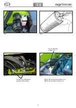
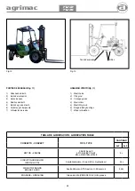
MANDOS (Fig 1, 2, 3 y 4)
1. - Asiento
2. - Mando de apertura de la plataforma
3. - Mando desplazador del mástil
4. - Mando movimientos del mástil
5. - Volante
6. - Cuadro de instrumentos
7. - Llave de contacto y arranque
8. - Caja de fusibles
9. - Depósito de líquido de frenos
10. - Pedal de acelerador
11. - Pedal de freno / inching
12. - Tapón llenado aceite hidráulico
13. - Mando de inversor
14- - Pulsador freno de estacionamiento
15. - Boca de llenado de combustible
16. - Visor de nivel de aceite hidráulico
17. - Nivel de combustible
PUESTA EN MARCHA DEL MOTOR
ATENCION
LA PUESTA EN MARCHA DEL MOTOR, ÚNICAMENTE SE DEBE
REALIZAR DESDE EL PUESTO DE CONDUCCIÓN
Para la puesta en marcha del motor operar de la siguiente forma:
1) Acceder al puesto de conducción y regular el asiento
adecuadamente al conductor.
2) El asiento dispone de regulación longitudinal.
3) Situar el mando del inversor (13) en posición NEUTRAL
y asegurarse de que las horquillas del mástil están abajo.
4) Introducir la llave de arranque y girarlo a la posición de contacto
(se encienden las luces de testigo del cuadro de instrumentos).
ATENCION
LA MÁQUINA DISPONE DE UN DISPOSITIVO DE SEGURIDAD QUE
IMPIDE ARRANCAR EL MOTOR MIENTRAS QUE EL MANDO DEL
INVERSOR NO ESTÉ SITUADO EN LA POSICIÓN NEUTRAL
5) Una vez ASEGURADO de que no existe NADIE en la zona de
acción de la máquina, girar la llave a la posición de arranque
(START).
Una vez que el motor se ha puesto en marcha, soltar la llave para que
vuelva a la posición inicial (contacto).
Si el motor no se pone en marcha, no insistir con arranques
prolongados durante mas de 15 segundos. Para no descargar la
batería, efectuar las pruebas sucesivas, dejando algunos intervalos y
repetir la operación después de haber controlado:
a) Que el filtro de combustible no esté obstruido
b) Que la batería esté en perfectas condiciones
c) Que hay suficiente combustible en el depósito
6) Antes de poner en marcha la máquina, mantener el motor
en ralentí 5 minutos. Es IMPORTANTE respetar esta indicación,
al inicio de la jornada y especialmente durante el período de
rodaje.
INSTRUCCIONES DE USO
CONTROLS (Fig 1, 2, 3 and 4)
1.- Seat
2.- Platform opening hand lever
3.- Auxiliary distributor control
4.- Mast movement control
5.- Steering wheel
6.- lnstrument panel
7.- Contact and ignition key
8.- Fuse box
9.- Brake fluid container
10.- Accelerator pedal
11.- Brake pedal/lnching
12.- Hydraulic oil filling plug
13.- lnverter lever
14.- Parking brake lever
15.- Fuel tank filling
16.- Hydraulic oil level rod
17.- Fuel tank level
STARTING THE ENGINE
ATTENTION
START THE ENGINE ONLY FROM THE DRIVING POST.
To start the engine, proceed as follows:
1) Occupy the driving post and adjust the driver’s seat.
2) The seat is longitudinally adjustable.
3) Place the inverter control (13) in NEUTRAL position and ensure
that the mast forks are down.
4) lnsert the ignition key and rotate it to the contact position (the
instrument panel controllights will turn on).
ATTENTION
THE MACHINE IS EQUIPPED WITH SAFETY DEVICES THAT
PREVENTE STARTING THE ENGINE WHILE:
THAT THE INVERSOR CONTROL IS NOT IN NEUTRAL
POSITION.
5) Once you are sure there is nobody in the area of action
of the machine, turn the starting key towards the rear (heater
position).
Then turn it towards the front (START).
lf the engine fails to start do not insist through extended attempts
lasting more than 15 seconds. In order to avoid discharging
the battery, try starting the engine, allowing time intervals, after
checking:
a) That the fuel filter is not obstructed.
b) That the battery is in perfect arder.
c) That there is sufficient fuel in the fuel tank.
6) Before putting the machine in motion, keep the engine at idling
speed for 5 minutes. This is IMPORTANT at the beginning of
the day, particularly in the Running-in period.
OPERATING INSTRUCTIONS
Содержание Carretillas Elevadoras TW12
Страница 2: ...2 agrimac TW12 TW16 Mayo 2019 ...
Страница 12: ...12 agrimac TW12 TW16 INDICADORES INDICATORS 11 ADELANTE FRONT ATRAS REVERSE 1 2 3 4 5 6 7 10 8 9 Fig 0 Fig 0 ...
Страница 14: ...14 agrimac TW12 TW16 Fig 1 Fig 2 Fig 3 Fig 4 1 2 10 12 11 13 14 15 16 3 4 5 6 7 8 9 17 ...
Страница 16: ...16 agrimac TW12 TW16 ...
Страница 18: ...18 agrimac TW12 TW16 Fig 6 Fig 7 3 4 ...
Страница 31: ...31 agrimac TW12 TW16 Fig 17 N º Bastidor Chasis number Placa de fabricante Manufacturer s plate ...
Страница 33: ...33 agrimac TW12 TW16 ESQUEMA ELÉCTRICO ELECTRIC SCHEME ...
Страница 34: ...34 agrimac TW12 TW16 ESQUEMA HIDRÁULICO 4x2 2WD HYDRAULIC SCHEME ...
Страница 35: ...35 agrimac TW12 TW16 ESQUEMA HIDRÁULICO 4x4 4WD HYDRAULIC SCHEME ...
Страница 39: ...39 agrimac TW12 TW16 ...


