


Chapter 12
263
Peripheral Devices
N5102A Digital Signal Interface Module
6.
Press the
Clock Phase
softkey.
From the menu that appears, you can adjust the phase of the clock relative to the data in
90 degree increments. The selections provide a coarse adjustment for positioning the clock on the
valid portion of the data. Selecting 180 degrees is the same as selecting a negative clock polarity.
The 90 degree and 270 degree selections are not available when the clock rate is set below
10 MHz or above 200 MHz. If 90 degrees or 270 degrees is selected when the clock rate is set
below 10 MHz or above 200 MHz, the phase will change to 0 degrees or 180 degrees, respectively.
NOTE
The clock phase and clock skew may need to be adjusted any time the clock rate setting is
changed. Refer to
“Clock Timing for Phase and Skew Adjustments” on page 251
.
7.
Enter the required phase adjustment.
8.
Press the
Return
softkey to return to the clock setup menu.
9.
Press the
Clock Skew
softkey.
This provides a fine adjustment for the clock relative to its current phase position. The skew is a
phase adjustment using increments of time. This enables greater skew adjustment capability at
higher clock rates. For clock rates below 25 MHz, this softkey is inactive.
The skew has discrete values with a range that is dependent on the clock rate. Refer to
“Clock
Timing for Phase and Skew Adjustments” on page 251
for more information on skew settings.
10. Enter the skew adjustment that best positions the clock with the valid portion of the data.
11. Press the
Clock Polarity Neg Pos
softkey to Neg.
This shifts the clock signal 180 degrees, so that the data starts during the negative clock
transition. This has the same affect as selecting the 180 degree phase adjustment.
12. Make the clock polarity selection that is required for the device being tested.
13. Press the
Return
hardkey to return to the first- level softkey menu.
The clock source selection is also reflected in the first- level softkey menu graphic. For example, if
the device is the new clock source, the graphic will show that the frequency reference is now
connected to the DUT and the DUT has an input clock line going to the N5102A module.
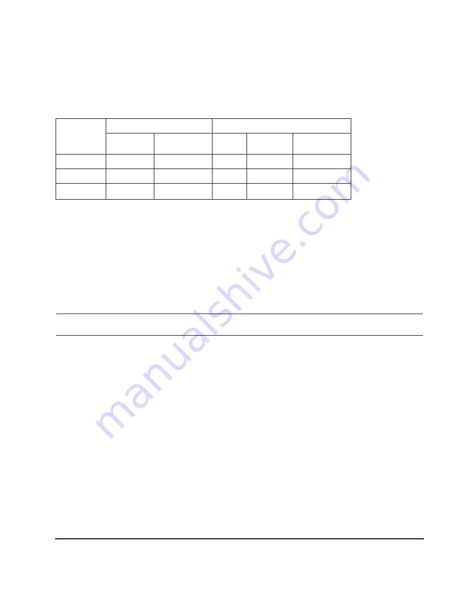
Table 12-8 Clock Source Settings and Connectors
Clock Source
Softkeys
N5102A Module Connection
Reference
Frequency
Clock Rate
a
a.For the Internal selection, this sets the internal clock rate. For the External and Device selections, this tells the
interface module the rate of the applied clock signal.
Freq Ref
Ext Clock In
Device Interface
External
•
•
Device
•
•
Internal
b
b.There should be no clock signal applied to the Ext Clock In connector.
•
•
•
Содержание E8257D
Страница 1: ...Agilent Technologies Agilent Technologies E8257D 67D E8663D PSG Signal Generators User s Guide ...
Страница 12: ...Contents xii ...
Страница 50: ...36 Chapter 1 Signal Generator Overview Rear Panel ...
Страница 92: ...78 Chapter 2 Basic Operation Using the Web Server ...
Страница 136: ...122 Chapter 3 Basic Digital Operation Using Waveform Clipping Figure 3 15 Rectangular Clipping ...
Страница 164: ...150 Chapter 4 Optimizing Performance Optimizing Phase Noise and Harmonics Below 3 2 GHz Option UNX UNY ...
Страница 194: ...180 Chapter 6 Custom Arb Waveform Generator Configuring Hardware ...
Страница 234: ...220 Chapter 8 GPS Modulation Option 409 Real Time GPS ...
Страница 244: ...230 Chapter 9 Multitone Waveform Generator Creating Viewing and Optimizing Multitone Waveforms ...
Страница 288: ...274 Chapter 12 Peripheral Devices Millimeter Wave Source Modules Figure 12 21 E8257D PSG without Option 1EA 1EU or 521 ...


