


Chapter 3
107
Basic Digital Operation
Using Waveform Markers
2.
Toggle the markers as desired:
a.
Highlight the first waveform segment.
b.
Press
Enable/Disable Markers
.
c.
As desired, press
Toggle Marker 1
,
Toggle Marker 2
,
Toggle Marker 3
, and
Toggle Marker 4
.
Toggling a marker that has no marker points (
page 104
) has no effect on the auxiliary
outputs.
An entry in the
Mkr
column (see figure below) indicates that the marker is enabled for that
segment; no entry in the column means that all markers are disabled for that segment
d. In turn, highlight each of the remaining segments and repeat
Step c
.
3.
Press
Return
.
4.
Name and store the waveform sequence (
Step 3
on
page 93
).
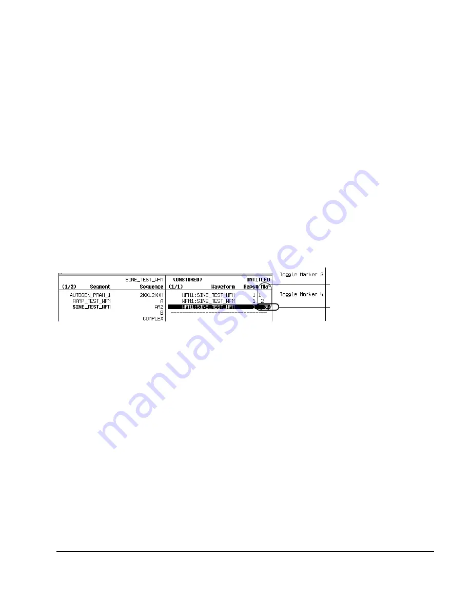
The following figure shows a sequence built reusing the same factory–supplied waveform segment; a
factory–supplied segment has a marker point on the first sample for all four markers. In this
example, Marker 1 is enabled for the first segment, Marker 2 is enable for the second segment, and
markers 3 and 4 are enabled for the third segment.
For each segment, only the markers enabled for that segment produce a rear panel auxiliary output
signal. In this example, the Marker 1 auxiliary signal appears only for the first segment, because it is
disabled for the remaining segments. The Marker 2 auxiliary signal appears only for the second
segment, and the marker 3 and 4 auxiliary signals appear only for the third segment.
In an Existing Waveform Sequence
If you have not already done so, create and store a waveform sequence that contains at least three
segments (
page 93
). Ensure that the segment or segments are available in volatile memory (
page 96
).
1.
Press
Mode
>
Dual ARB
>
Waveform Sequences
, and highlight the desired waveform sequence.
2.
Press
Edit Selected Waveform Sequence
, and highlight the first waveform segment.
3.
Press
Enable/Disable Markers
>
Toggle Marker 1
,
Toggle Marker 2
,
Toggle Marker 3
, and
Toggle Marker 4
.
Toggling a marker that has no marker points (
page 104
) has no effect on the auxiliary outputs.
An entry in the
Mkr
column indicates that the marker is enabled for that segment; no entry in the
column means that all markers are disabled for that segment
4.
Highlight the next waveform segment and toggle the desired markers (in this example, markers 1
and 4).
5.
Repeat
Step 4
as desired (for this example, select the third segment and toggle marker 3).
6.
Press
Return
>
Name And Store
>
Enter
.
Sequence Marker Column
This entry shows that
markers 3 and 4 are enabled
for this segment.
Содержание E8257D
Страница 1: ...Agilent Technologies Agilent Technologies E8257D 67D E8663D PSG Signal Generators User s Guide ...
Страница 12: ...Contents xii ...
Страница 50: ...36 Chapter 1 Signal Generator Overview Rear Panel ...
Страница 92: ...78 Chapter 2 Basic Operation Using the Web Server ...
Страница 136: ...122 Chapter 3 Basic Digital Operation Using Waveform Clipping Figure 3 15 Rectangular Clipping ...
Страница 164: ...150 Chapter 4 Optimizing Performance Optimizing Phase Noise and Harmonics Below 3 2 GHz Option UNX UNY ...
Страница 194: ...180 Chapter 6 Custom Arb Waveform Generator Configuring Hardware ...
Страница 234: ...220 Chapter 8 GPS Modulation Option 409 Real Time GPS ...
Страница 244: ...230 Chapter 9 Multitone Waveform Generator Creating Viewing and Optimizing Multitone Waveforms ...
Страница 288: ...274 Chapter 12 Peripheral Devices Millimeter Wave Source Modules Figure 12 21 E8257D PSG without Option 1EA 1EU or 521 ...


