


90
E5505A Installation Guide
A
Service, Support, and Safety Information
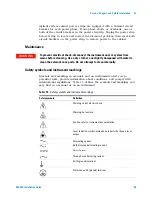
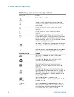
Frame or chassis terminal.
Terminal is at earth potential. Used for measurement and
control circuits designed to be operated with one terminal at
earth potential.
Terminal for neutral conductor on permanently installed
equipment.
Terminal for line conductor on permanently installed
equipment.
Standby (supply); units with this symbol are not completely
disconnected from AC mains when this switch is in the standby
position. To completely disconnect the unit from AC mains,
either disconnect the power cord, or have a qualified/licensed
electrician install an external switch.
OFF (supply); a switch with this symbol opens the instrument’s
power supply circuit, disconnecting it with the mains supply.
ON (supply); a switch with this symbol closes the instrument’s
power supply circuit, connecting it with the mains supply.
Instrument markings
Definition
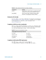
The CE mark is a registered trademark of the European
Community.
This symbol indicates compliance with the China RoHS
regulations for paper/fiberboard packaging.
China RoHS regulations include requirements related to
packaging, and require compliance to China standard GB
18455-2001.
This symbol indicates separate collection for electrical and
electronic equipment, mandated under EU law as of August 13,
2005. All electric and electronic equipment is required to be
separated from normal waste for disposal. (Reference WEEE
Directive, 2002/96/EC).
The CSA mark is a registered trademark of the
CSA-International. This instrument complies with Canada CSA
22.2 No. 61010-1-04.
The C-tick mark is a registered trademark of the Spectrum
Management Agency of Australia. This signifies compliance
with the Australian EMC Framework regulations under the
terms of the Radio Communications Act of 1992.
Table 15
Safety symbols and instrument markings (continued)
Safety symbols
Definition
N10149
Содержание E5505A
Страница 18: ...18 E5505A Installation Guide 1 General Information ...
Страница 22: ...22 E5505A Installation Guide 2 Flat Panel Display ...
Страница 30: ...30 E5505A Installation Guide 3 System Interconnections ...
Страница 70: ...70 E5505A Installation Guide 5 Recovery Figure 39 Ejector Lever Pulled Up Figure 40 Ejector Lever Pushed Down ...
Страница 84: ...84 E5505A Installation Guide 6 Preventive Maintenance ...
Страница 96: ...96 E5505A Installation Guide A Service Support and Safety Information ...


