58
59
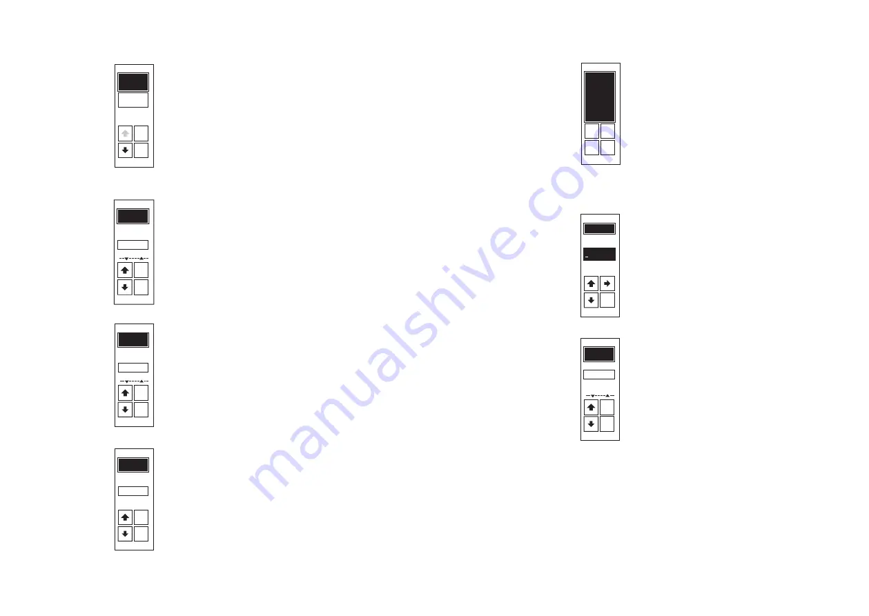
Load type, dynamic of the load:
This screen appears only if the configuration R-Load has
been selected beforehand.
When configuring a load with heat inertia load with
Slow (T
0
= 1 s) the distance between the ignition cycles
increases so that the switch on and switch off duration
lasts longer. In the case of loads which are thermally easy
to influence by external effects, the switching time can
be shortened by configuring Fast (T
0
= 0.1 s) to achieve a
more even warm up.
Load type, connection:
Depending on the connection option the adequate entry
has to be chosen from the list. This is important for the
accurate processing and displaying of data. Potential
necessary changes of the connection can be taken from
chapter 5.2. Load configuration.
Operating mode:
The operating mode can be set as
QTM, Switch, TAKT
or
VAR
. At this the settings for the load type are taken into
consideration. Notes on operating modes can be taken
from the chapter Operating modes.
Control mode:
The type of control can be set, the selection includes
I,
I², U, U², P
and
Off
. Notes on control mode can be
taken from the chapter Control modes.
Control end value:
This screen only appears if the control mode has been
selected beforehand, not if Off is selected.
The control end value is the maximum value for control and
limitation. In the case of full control through the setpoint
this value defines the maximum which can be reached at
the output. The unit is dependent on the control mode. In
the case of voltage based control it is U
max
in V, with current
based control it is I
max
in A, and with power based control it
is P
max
in W. In most cases the preconfigured value is suffici-
ent and can be confirmed with the NO button.
Control end value, value input:
This screen only appears when the YES button has been
selected beforehand.
Similar to the unit from the previous screen an input field
appears for the desired value of the control end value.
After inputting all positions of the value the OK button
appears to confirm.
Control signal:
The correct input variable must be selected correspon-
ding to the signal for the setpoint definition. The selected
value is related to the 1
st
analog setpoint. The 2
nd
analog
setpoint remains set to 0-5V in order to enable an offset
through the addition of the setpoints using an external
potentiometer. The 3 analog outputs also receive the
variable of the setpoint selected here. The configuration
for the 2
nd
analog setpoint can be changed afterwards
in EasyStart. The electrical limits of the levels must be
heeded.
Содержание THYRO-AX
Страница 117: ...118...


