User Manual of TV5600-B01 Series Dispensing Control System
116
andmodification
16
IN14
External
reset,
allow
configuration
and
modification
16
IN31
17
IN15
External
pause,
system
configuration required
17
IN32
18
IN16
Universal input
18
IN33
※
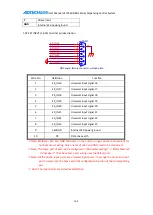
Note: The home port of each axis is configured in “Factory parameters” ->“Motor features”
->“Homeport”. The above home port wiring uses the default port.
※
Note: All the above input ports are universal input ports. To occupy the home and limit
ports, simply turn the home and limit configuration function of the corresponding
axis.
2. Input port wiring method
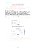
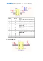
Controller internal input port diagram:
Controller general input connection: (PV switch V means VCC, G means GND, O means
output)
The INCOM terminal is connected to the positive terminal of the external power supply, and the
input signal is connected to the corresponding terminal pin. The common end of IN0-IN16 is
INCOM1; the common end of IN17-IN33 is INCOM2; when used, the common end needs to be
connected to +24V power supply, the input point is low level effective, and the current of single
input does not exceed 15mA and isn’tless than 5 mA.
Содержание DJ1600V1-A01
Страница 1: ...I TV5600 B01 Series Dispensing Control System User Manual ...
Страница 2: ...User Manual of TV5600 B01 Series Dispensing Control System 2 ...
Страница 15: ...User Manual of TV5600 B01 Series Dispensing Control System 15 Front view Side view Side view ...
Страница 47: ...User Manual of TV5600 B01 Series Dispensing Control System 47 ...
Страница 123: ...User Manual of TV5600 B01 Series Dispensing Control System 123 ...
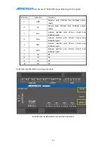
Страница 131: ...User Manual of TV5600 B01 Series Dispensing Control System 131 8 AMC1600serial port AMC1600 COM1 port ...


