User Manual of TV5600-B01 Series Dispensing Control System
104
7
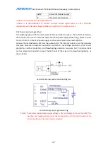
Rtravel limit
GND
Internal 24V power ground
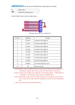
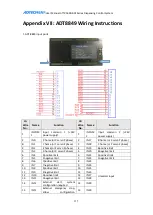
1.02 EXT INPUT (16-23) terminal pin description
Wire No.
Definition
Function
1
EX_IN16
Universal input signal 16
2
EX_IN17
Universal input signal 17
3
EX_IN18
Universal input signal 18
4
EX_IN19
Universal input signal 19
5
EX_IN20
Universal input signal 20
6
EX_IN21
Universal input signal 21
7
EX_IN22
Universal input signal 22
8
EX_IN23
Universal input signal 23
9
24VGND
Internal 24V power ground
10
PE
Protective earth
※
Note: Multiple +24V and GND terminals on the common input port are convenient for
multiple sensor wiring. Only one set of +24V and GND need to be connected.
※
Note: The home port of each axis is configured in “Parameter settings” ->“Motor features”
->“Homeport”. The above home port wiring uses the default port.
※
Note: All the above input ports are universal input ports. To occupy the home and limit
ports, simply turn the home and limit configuration function of the corresponding
axis.
※
Note: The input points are all low level effective.
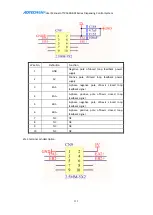
COM1
DB9 angle, female connector, welded plate
5
9
4
8
3
7
2
6
1
10
EX_IN23
EX_IN22
EX_IN19
EX_IN21
EX_IN16
EX_IN17
EX_IN18
EX_IN20
Содержание DJ1600V1-A01
Страница 1: ...I TV5600 B01 Series Dispensing Control System User Manual ...
Страница 2: ...User Manual of TV5600 B01 Series Dispensing Control System 2 ...
Страница 15: ...User Manual of TV5600 B01 Series Dispensing Control System 15 Front view Side view Side view ...
Страница 47: ...User Manual of TV5600 B01 Series Dispensing Control System 47 ...
Страница 123: ...User Manual of TV5600 B01 Series Dispensing Control System 123 ...
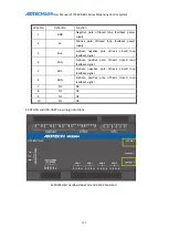
Страница 131: ...User Manual of TV5600 B01 Series Dispensing Control System 131 8 AMC1600serial port AMC1600 COM1 port ...

