User Manual of TV5600-B01 Series Dispensing Control System
109
AXIS-2
Function
A+
Stepping motor A+end
A-
Stepping motor A-end
B+
Stepping motor B+end
B-
Stepping motor B-end
System R axis
AXIS-3
Function
A+
Stepping motor A+end
A-
Stepping motor A-end
B+
Stepping motor B+end
B-
Stepping motor B-end
※
Note: The DRIVER POWER terminal is the drive motor power supply, and only one set of VDC
and GND needs to be connected.
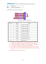
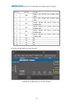
3.02 Four-axis closed-loop feedback signal input wiring definition
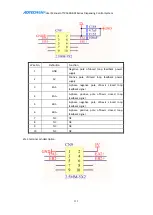
EN-0 terminal pin description:
Wire No.
Definition
Function
1
GND
Negative pole ofclosed loop feedback power
supply
2
5V
Positive pole ofclosed loop feedback power
supply
3
EA3-
A-phase negative pole ofZ-axis closed loop
feedback signal
4
EA3+
A-phase positive pole ofZ-axis closed loop
feedback signal
5
EB3-
B-phase negative pole ofZ-axis closed loop
feedback signal
6
EB3+
B-phase positive pole ofZ-axis closed loop
feedback signal
Содержание DJ1600V1-A01
Страница 1: ...I TV5600 B01 Series Dispensing Control System User Manual ...
Страница 2: ...User Manual of TV5600 B01 Series Dispensing Control System 2 ...
Страница 15: ...User Manual of TV5600 B01 Series Dispensing Control System 15 Front view Side view Side view ...
Страница 47: ...User Manual of TV5600 B01 Series Dispensing Control System 47 ...
Страница 123: ...User Manual of TV5600 B01 Series Dispensing Control System 123 ...
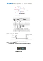
Страница 131: ...User Manual of TV5600 B01 Series Dispensing Control System 131 8 AMC1600serial port AMC1600 COM1 port ...


