ADT-09 Series Motion Control Card
29
3.2.
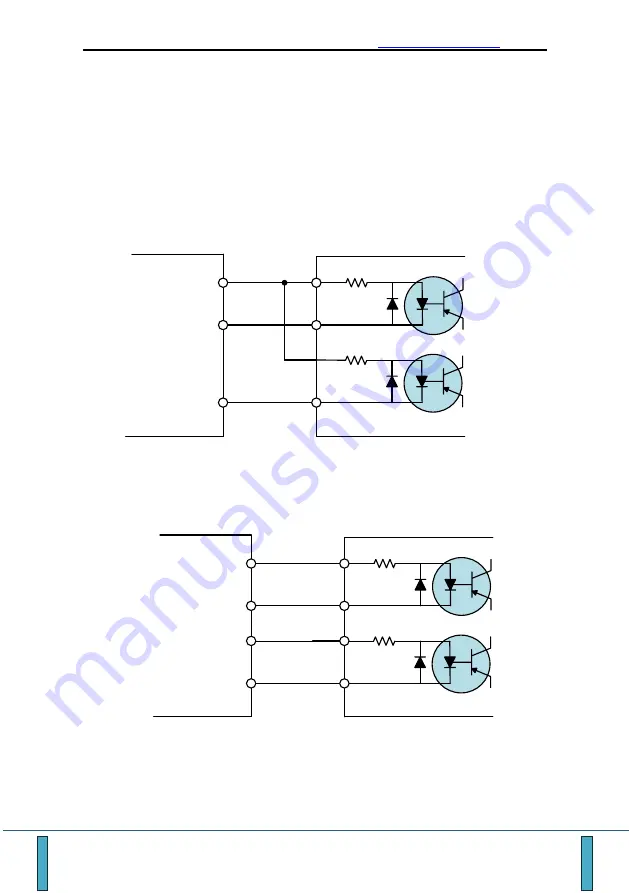
Connecting pulse/direction output signal
Pulse output is differential output, and can be easily connected to the
stepper / servo drives.
The figure below shows the connection between the pulse and the
anode of the direction. PUCOM is the 7th pin of the 25-pin DB connector
(+5V power output). To enhance the anti-interference ability of the
common anode connection, it is recommended to connect the DB side
+5V GND (Pin 10/13/20/21/24) to the driver terminal ground wire.
PUCOM
Step motor driver
PU-/CW-
DR-/CCW-
PU+
PU-
DR+
DR-
Below is independent connection of pulse and direction signal. Differential
connection is recommended due to strong anti-interference.
PU+/CW+
Step motor driver
PU-/CW-
DR-/CCW-
PU+
PU-
DR+
DR-
DR-/CCW-


