FR
WMBus Smart Building MOTION - Guide utilisateur / User guide version V1.0.0
4
Page
of 82
FR
ENGLISH 41
PRODUCTS AND REGULATORY INFORMATION
42
1.
DEVICE OVERVIEW
47
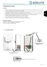
1.1. General description
47
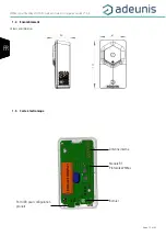
1.2. Dimensions
48
1.3. Electronical board
48
1.4. Technical Specifications
49
1.4.1 General characteristics
49
1.4.2 Autonomy
49
1.4.3 Digital input interfaces
50
1.4.4 Characteristics of the embedded sensors
50
2.
DEVICE OPERATION
51
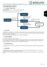
2.1. Operating modes
51
2.1.1 PARK MODE
51
2.1.2 COMMAND MODE
51
2.1.3 OPERATING MODE
51
2.1.4 REPLI MODE
51
2.1.5 Three transmission modes to meet needs
52
2.1.6 Transmitting the Keep Alive frame
58
2.1.7 Digital Input alarm(s)
58
2.2. Operation of the LEDs
59
3.
DEVICE CONFIGURATION
60
3.1. Iot Configurator
60
3.2. Advanced Mode
60
3.2.1 Connecting the device to a computer
60
3.2.2 Command mode
61
3.2.3 AT Command
62
3.3. Description of the registers
63
3.3.1 Function registers
63
3.3.2 WMBus Network Registers
66
4.
DESCRIPTION OF FRAMES
68
4.1. Format of the WMBUS frame
68
4.2. Uplink frames
68
4.2.1 Fixed bytes
68
4.2.2 Information frames on device configuration
69
4.2.3 Information frame on configuration of Digital Input(s)
70
4.2.4 Information frames on Network configuration
70
4.2.5 Keep alive frame
70
4.2.6 Periodic data frame
71
4.2.7 Presence detection alarm frame
71
4.2.8 4.2.8
Brightness alarm frame
72
4.2.9 Alarm frame for Digital inputs
72
4.2.10
Summary of the conditions for sending uplink frames
73
5.
INSTALLATION AND START-UP
74
5.1. Opening and closing the unit
74
5.2. Configuring the device
74
5.3. Replacing the battery
75
5.4. Cabling Digital Input 2 via the terminal block
75
5.5. Correct positioning of the device
76
5.6. Fixing with screws
76
5.7. Starting up the device using the button
76
6.
DOCUMENT VERSIONS
77
DEUTSCH VORSCHRIFTEN
78


