


EN
WMBus Smart Building MOTION - Guide utilisateur / User guide version V1.0.0
69
Page
of 82
FR
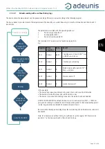
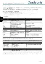
4.2.1.02
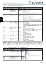
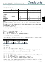
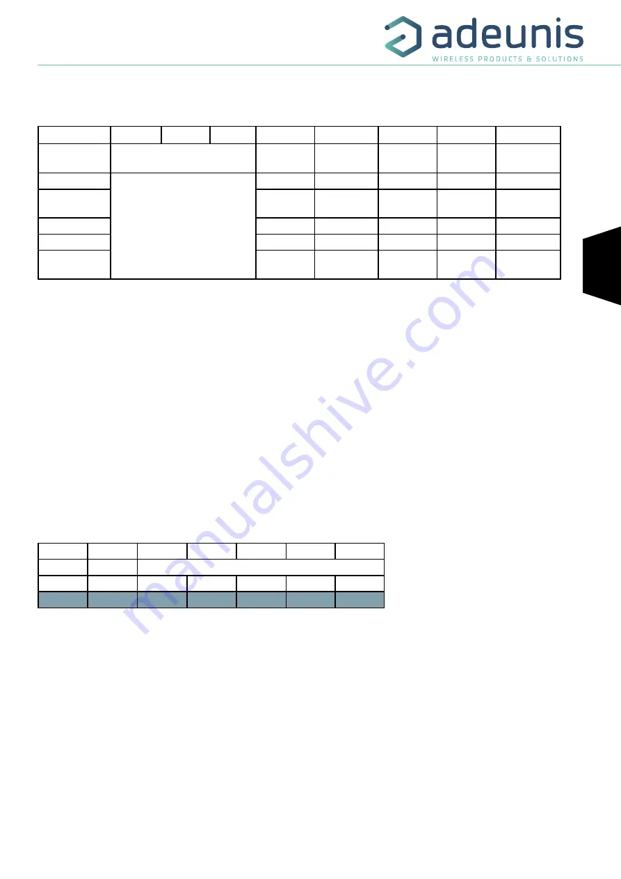
Status byte
The Status Byte is broken down as follows:
Alarms status
Bit 7
Bit 6
Bit 5
Bit 4
Bit 3
Bit 2
Bit 1
Bit 0
Frame counter
Reserved
Configuration
inconsistency
Hardware
error
Low battery
Configuration
successful
No error
0x00 to 0x07
X
0
0
0
X
Configuration
successful
X
0
0
1
X
Low battery
X
0
1
0
X
Hardware error
X
1
0
0
X
Configuration
inconsistency
X
1
0
0
0
Field details:
• Frame counter: it increments on each broadcast and allows you to quickly see if a frame has been lost. It counts from 0 to 7 before looping
back.
• Hardware error: this bit is set when a hardware error has occurred, for example an EEPROM write problem, a reading problem on the ADC ...
The device must be returned to After-Sales Service.
• Low battery: 1 bit if low battery, otherwise 0.
• Set up successful: bit set to 1 if a configuration was performed during the last downlink, otherwise 0. This bit returns to 0 from the next frame.
• Configuration inconsistency: readings lost in periodic mode because the size of the data available in the frame does not allow it to send all the
requested values in the configuration of the history.
E.g.:
A value of the status byte equal to 0xA3 (= 10100011 in binary) gives:
• Bit 7 to 5 = 101 = 0x05 i.e. a frame counter at 5
• Bit 4 to 0 = 00011 in binary, i.e. a low-battery alarm and the validation of the configuration.
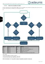
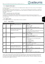
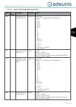
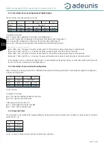
4.2.2 Information frames on device configuration
When switching to operating mode (PARK or COMMAND mode output), the following frame (0x10) representing the application configura-
tion of the device is transmitted:
0
1
2 & 3
4 & 5
6 & 7
8 & 9
10 & 11
Code
Status
PAYLOAD
0x10
See Statut
S300
S301
S320
S321
S322
0x10
0xA3
0x21C0
0x0008
0x0012
0x012C
0x0001
Its size is 10 bytes.
Description of the frame:
Bytes 2 and 3: register 300, transmission period of the keep alive frame
Bytes 4 and 5: register 301, transmission period of the periodic data in number of backups to be made before transmission of a frame
Bytes 6 and 7: register 320, backup period: number of readings (polls) to be made before doing a backup (logging).
Bytes 8 and 9: register 321, data acquisition period (polling period)
Bytes 10 and 11: register 322, waiting period of the sensor before allowing detection again (x10 sec)
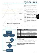
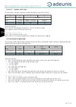
In the example in grey, this results in:
Bytes 2 and 3: S300 = 0x21C0 i.e. 8640 in decimal, the transmission period of the keep alive frame is equal to 8640x10 = 8640 secs or 24h.
Bytes 4 and 5: S301 = 0x0008 i.e. 8 in decimal
Bytes 6 and 7: S320 = 0x0012 i.e. 18 in decimal Bytes 8 and 9: S321 = 0x012C i.e. 300 in decimal
Bytes 10 and 11: S322 = 0x0001 i.e. 1 in decimal, or a waiting time of 10 seconds from the end of detection
In the example the device will take a reading every 10 minutes (300 seconds), will make a backup every 18 readings every 3 hours (18x300
sec = 3 hours) and send a data frame every 24 hours (8 x 3 hours = 24 hours).