


EN
WMBus Smart Building MOTION - Guide utilisateur / User guide version V1.0.0
68
Page
of 82
FR
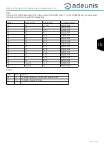
4. DESCRIPTION OF FRAMES
The device transmits raw information from the sensors using the Wireless M-BUS protocol.
In this chapter, you will find information for decoding the Wireless M-Bus frame as well as other useful data.
IMPORTANT NOTE: The device does not interpret or decode information from the sensor. Decoding as a value and/or unit is the responsibility of
the user once the radio frame has been received via its receiver.
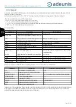
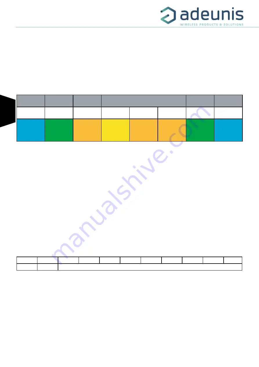
4.1. Format of the WMBUS frame
The format of the WMBUS frame is unique and based on the division below:
L-Field
C-Field
M-Field
A-Field
CI
Field
Data-Field
Frame size
Control
Manufacturer
ID
Device serial
number
Version
Device type
Frame code
Payload
32
44
46 06
33 22 11 00
56
00
AA
Content
described in
the following
paragraphs
Field description:
- L-Field: indicates the length of the Data Field, in the example 0x32 = 50 bytes
- C-Field: indicates the frame type (always equal to 0x44 for SEND / NO REPLY)
- M-Field: indicates the manufacturer code, BCD encoding here in example 06 46 (ARF)
- A-Field contains
o The 8-character device serial number (visible on the label), BCD encoding. In the example above (0x33221100) the device has the serial
number 00112233
o Version is the user-configurable version number in the S227 register, here 0x56
o Device type indicates the user-configurable device type in the S227 register, here 0x00
- CI Field: indicates the frame code (always equal to 0xAA)
- Data Field contains the uplink frames described below.
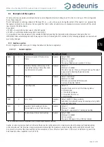
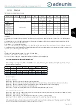
4.2. Uplink frames
The uplink frames of the device to the network have a variable size according to the transmitted information.
4.2.1 Fixed bytes
The first two bytes of the frame systematically indicate the frame code and status as shown below:
0
1
2
3
4
5
6
7
8
9
10
Code
Statut
PAYLOAD
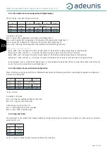
4.2.1.01
Byte code
This byte contains the frame code to make it easier for the information system to decode the frame.