USER’S MANUAL
V-line 899x.xxx/LPG HYBRID
50
check valve prevents permanent supply of stored fuels into the pumping monoblock when the
dispenser is out of operation.
The pumping monoblock of dispensers (P 640 type) is designed with air separator permanently open
to the deaerating chamber formed by the space in the monoblock body and the space of the
monoblock cover. There is a hole in the upper wall of the cover with integrated DN 6 adapter for
connecting the air outlet pipe (OT).
To eliminate the overfilling of the deaeration chamber of the pumping monoblock and discharging of
fuel into the interior of the dispenser and consequently into its close area in case of the leakage or
blocking of the check valve flap when the dispenser is out of operation, it is necessary to connect the
separator outlet of the pumping monoblock to the storage tank. This connection shall be carried out
by means of a tube (OT) min. 8 x 1 (DN 6) connected to the tube adapter DN 6. The tube adapter
with the gasket is screwed into the opening M 12 x 1,5 in the upper wall of the monoblock. The tube
outlet mouths in the tank above the level of the stored fuel. The connection shall be carried out by
means of the tube adapter DN 6 screwed into the tank cover (tapped hole M 12 x 1,5 in the tank
cover shall be made).
Closing the outlet opening of the pumping monoblock separator is not allowed. Accumulation of
separated air or fuel vapours and their sequential compression in this closed space of the pumping
monoblock or a change in the fuel volume owing to the ambient temperature increase can induce
excessive pressure in the hydraulic system. Thus blockage of the fuel dispensing or another defect
could occur.
A stop-valve (UV) of relevant nominal inside diameter shall be installed in the suction piping as close
to the dispenser as possible (e.g. in the shaft close to the dispenser).
Piping from air separator (OT – min. DN 6 – 8 x 1) install in the tank area above the level of storage
fuel.
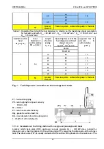
Scheme of the fuel dispenser installation – see fig. 2, 3 and 4.
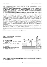
Fig. 2 - Fuel dispenser connection to
the overground tank
PT – fuel suction piping
VR – return piping for vapour recovery
(DN min. 20)
OT – piping from air separator (min. DN 6)
PZV – return valve (alternatively)
UV – stop-valve
DN – inner diameter of suction piping (mm)
L – lehgth of suction piping (m)
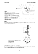
Fig. 3 – Example of the suction piping design for the connection of the fuel dispenser
to the overground tank
Содержание V-line 899 LPG HYBRID Series
Страница 2: ......
Страница 26: ...USER S MANUAL V line 899x xxx LPG HYBRID 20 Pic 6 Pic 7 ...
Страница 29: ...USER S MANUAL V line 899x xxx LPG HYBRID 23 Pic 15 Pic 16 ...
Страница 30: ...USER S MANUAL V line 899x xxx LPG HYBRID 24 Pic 10 Scheme of inputs and outlets of the unit VAPORIX Control ...

