USER’S MANUAL
V-line 899x.xxx/LPG HYBRID
25
4.5.6.
Function of system VRC with VRMS
Function of system VRC-M with VRMS
Function of system VRC-M
The vacuum in the VRC-M system is created plunger vacuum pump (Item 2), which is powered via a rubber
belt electric pumping monoblock. For dispensers with pressure system is installed in a compact unit with
integrated electric pump.
Outgoing petrol vapors from the tank car when dispensing petrol are drawn special adapter nozzle (item
7), through the channel in the body to control flow through the gun hydromechanical valve integrated into
nozzle and into the inner coaxial hose DN 8 (Item 6). The coaxial spacer (Item 5) pairs are fed to a flexible
connecting pipe (Item 4), then proceed to the measurement sensor VAPORIX-Flow (poz.9) and then
connecting flexible pipe (Item 3) to the piston pump (pos. 2). The piston pump (item 2) are pushed
through a flexible pipe (Item 1) into the duct connected to the vapor inside the storage tank (usually from
the lowest octane petrol).
Optimal flow of vapor is dynamically regulated proportional hydromechanical valve depending on the
actual flow of liquid petrol nozzle.
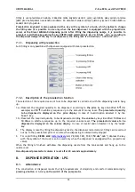
Proper function of vapor recovery is indicated by shining symbol of two arrows (Fig. 9) on the display of
electronic counter on the appropriate side of the dispenser.
Pic. 3
Pic. 4
System VRC non functional
System VRC is functional
Function of system VRMS:
Automatic Monitoring System (VRMS) VAPORIX dynamically controls the system to function properly VRC.
Measuring sensor VAPORIX-Flow (Item 9) indicates the instantaneous flow and vapor flow rates found
online transmitted to the evaluation unit VAPORIX-Control (Item 10), which compares these values with
the values given volume of liquid petrol from the transmitted pulse output electronic counter (Item 8) into
the VAPORIX-Control - Connection Figure 6 (Item 4).
The operational statue of the system can notify the operator VRMS at the kiosk station via electronic
unit VAPORIX-Master, which is usually located near the pumping station control system - POS.
VAPORIX-Control Units and VAPORIX-Master are communicatively connected via RS 485 interface using
a communication cable.
Function of system VRC-E with VRMS
Function of system VRC-E
The vacuum in the system VRC-E is generated plunger vacuum pump (Item 2), which is powered via a
rubber belt electric pumping monoblock. For dispensers with pressure system is installed in a compact
unit with integrated electric vacuum pump.
Outgoing
petrol vapors from the tank car when dispensing petrol are drawn special adapter nozzle (Item
9), through the channel in the gun body flowing into the inner coaxial hose DN 8 (Item 8), attached to the
coaxial spacer (item 7). The coaxial spacer (item 7) are fed to the steam flexible connecting pipe (Item
6), then proceed to the measurement sensor VAPORIX-Flow (poz.11) and then connecting flexible pipe
(item 5) to control the proportional solenoid valve. The valve is kept flexible pipe (Item 3) to the piston
pump (Item 2). The piston pump (item 2) are pushed through a flexible pipe (Item 1) into the duct
connected to the vapor inside the storage tank (usually from the lowest octane petrol).
Содержание V-line 899 LPG HYBRID Series
Страница 2: ......
Страница 26: ...USER S MANUAL V line 899x xxx LPG HYBRID 20 Pic 6 Pic 7 ...
Страница 29: ...USER S MANUAL V line 899x xxx LPG HYBRID 23 Pic 15 Pic 16 ...
Страница 30: ...USER S MANUAL V line 899x xxx LPG HYBRID 24 Pic 10 Scheme of inputs and outlets of the unit VAPORIX Control ...


