Model TT235-0600
RTD/Resistance Thermometer Transmitter w/USB
Acromag, Inc. Tel: 248-295-0880
- 32 -
http://www.acromag.com
[
32
]
https://www.acromag.com
Output
…
Output DAC Resolution:
Output DAC is 16-bit and its output current is approximated
via the expression (programmed_count/65536)*24mA. The min loop current is
~3.5mA, typical, which is approximated via a DAC program count of 9120. Likewise,
4mA corresponds to a count value of ~10923, and 20mA to ~54613. Thus, for the 4-
20mA output range, we have an output resolution of 54613-10923, or 1 part in
43690. The effective I/O resolution of this transmitter will be the lowest resolution
of either the input, or the output.
Output Response Time:
Varies with input filter level for a step change in the input
signal (also varies with output load). Note: The ADC requires two samples to fully
characterize the input signal (see Input Sampling Rate).
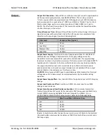
Filter Level
Response Time (Typical)
None
22ms
Low Filter
50ms
Medium Filter
160ms
High Filter
1210ms
Output Power Supply:
This device is output loop powered from 12
–
32VDC SELV
(Safety Extra Low Voltage), 24mA maximum. The supply voltage across the
transmitter must never exceed 36V, even with a shorted load. The supply voltage
level must be chosen to provide a minimum of full-scale current to the load (0.020*R
typical), plus 11V minimum to the transmitter terminals, plus any line drop. Ideally,
the supply should drive over-scale current levels up to 24mA into load. Reverse
polarity protection is inherent as output terminals are not polarized. The ± output
polarity labels on the enclosure are for reference only.
CAUTION:
Do not exceed 36VDC peak to avoid damage to the transmitter. Terminal
voltage above 11V minimum must be maintained across the transmitter during
operation.
Output Power Supply Effect:
Less than ±0.001% of output span per volt DC of supply
change.
Output Load Resistance Effect:
Less than ±0.001% of output span for a ±100Ω
change in load resistance.
Output Compliance and Load Resistance Equation:
11V minimum, transmitter.
Transmitter will drive 13V typical to the load with a 24V loop supply and 20mA loop
current (650Ω), assuming negligible line drop. Compute R
load
(Max) = (V
supply
–
11V)/0.020A for 20mA full-scale output current. Refer to the following table:
V
supply
Volts
Max R
load
w/20mA & No Line Drop
12V
50Ω
18V
350
Ω
24V
650
Ω
32V
1050
Ω
Ideally, it should be possible to drive the over-scale current of 24mA to the load and
this would yield a maximum load resistance of 540Ω for 24mA of loop current and a
24V loop supply.

