Model TT235-0600
RTD/Resistance Thermometer Transmitter w/USB
Acromag, Inc. Tel: 248-295-0880
- 7 -
http://www.acromag.com
[
7
]
https://www.acromag.com
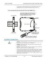
Strip back wire insulation 0.25-inch on each lead and insert the wire ends into the
cage clamp connector of the terminal block. Use a screwdriver to tighten the screw
by turning it in a clockwise direction to secure the wire (0.5-0.6Nm torque). Since
common mode voltages can exist on signal wiring, adequate wire insulation should
be used and proper wiring practices followed. As a rule, output wires are normally
separated from input wiring for safety, as well as for low noise pickup.
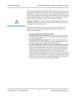
Important
–
End Stops:
For hazardous location installations (Class I, Division 2 or
ATEX/IECEx Zone 2) it must use two end stops (Acromag 1027-222) to secure the
module(s) to the DIN rail (not shown).
Sensor Input Connections
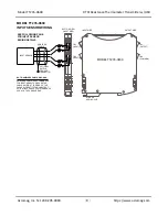
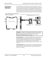
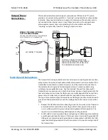
Sensor wires are connected directly to the transmitter input terminals at the
bottom of the transmitter (the spring-loaded DIN clip side), as shown in the
connection drawing below.
•
Transmitter input signal is isolated from output.
•
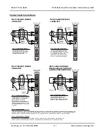
Three-wire input sensors require jumper:
For three-wire sensors (including
resistive elements), a copper jumper wire must be connected between input
pins 1 and 4 ([+] and [H]).
•
Two-wire input sensors require jumpers:
For a two-wire sensor (including
resistive elements), a copper jumper wire must be connected between input
pins 4 and 5 ([
–
] and [L]) as well as pins 1 and 4 ([+] and [H]).
•
Four-wire configuration eliminates error associated with lead-wire resistance:
A four-wire configuration allows the input sensor to be accurately measured
without having to compensate for the resistance of the lead-wires. RTDs are
typically measured by passing an excitation current through the RTD element
and relating the measured voltage drop across the RTD element with a
corresponding temperature. Because the lead-wires to the RTD element have
intrinsic resistance, a voltage drop is created in the lead-wires in addition to the
voltage drop across the RTD element. By using two dedicated wires to directly
measure only the RTD element, the voltage drop created by the resistance of
the lead-wires is removed from the measurement altogether.
!


