Model TT235-0600
RTD/Resistance Thermometer Transmitter w/USB
Acromag, Inc. Tel: 248-295-0880
- 25 -
http://www.acromag.com
[
25
]
https://www.acromag.com
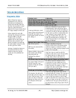
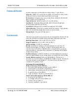
TROUBLESHOOTING
Diagnostics Table
Before attempting repair or
replacement, be sure that all
installation and configuration
procedures have been followed
and that the transmitter is wired
properly. Verify that power is
applied to the transmitter and that
the supply voltage is at least 11V.
If the problem still exists after
checking the wiring and reviewing
this information, or if other
evidence points to another
problem with the transmitter, an
effective and convenient fault
diagnosis method is to exchange
the questionable transmitter with
a known good transmitter.
Acromag’s
Application Engineers
can provide further technical
assistance if required. Repair
services are also available from
Acromag.
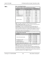
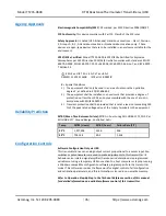
POSSIBLE CAUSE
POSSIBLE FIX
Cannot Communicate with Transmitter via USB…
Output shifts off-range when connect USB is connected
…
Output Erratic, Not operational, or at Wrong Value
…
Transmitter fails to operate or exhibits an output shift
…
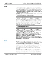
A missing USB Isolator could
cause a ground loop between a
grounded input sensor and
earth ground at the connected
PC’s
USB port.
Without a USB isolator, a ground loop is
possible between a grounded input signal
source and earth ground of the PC USB port.
It is best to connect to USB via a USB isolator
for this reason, and for increased safety and
noise immunity. Use an isolator like the
Acromag USB-ISOLATOR. Otherwise, use a
battery powered laptop to configure the
transmitter which does not normally earth
ground its USB port.
Software Fails to Detect Transmitter…
Bad USB Connection
Recheck USB Cable Connection
USB has not enumerated the
transmitter.
Use the reset button on the Acromag USB
isolator to trigger re-enumeration of the
transmitter, or simply unplug/re-plug the USB
cable to the transmitter.
Communication or power was
interrupted while USB was
connected with the
configuration software
running.
Close the current connection with the
software, select and re-open the transmitter
for communication (or simply exit the
configuration software and restart it).
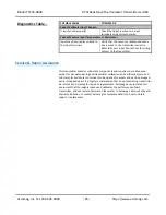
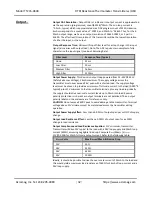
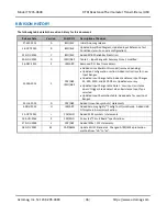
For an input step, the output appears to make 2 steps to reach its final value
…
For a step change in the input,
the ADC requires 2 input
samples to fully characterize
the input signal.
The ADC requires two samples to fully
characterize the input signal, and this is
evident when using a scope to examine the
output transition in response to a step
change at the input, which makes two steps
in its transition to its final level.
Output goes to Over-Range (24mA)) or Under-Range Limit (3.5mA)
…
This indicates that either the
input signal is out of range, or a
sensor lead has broken. It can
also occur due to contention
between earth ground at the
PC USB port and the input
sensor.
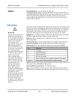
Check the input signal with respect to its
range and reduce or increase it as required to
drive the output within its linear operating
range. A fully Over-Range or Under-Range
signal can be driven by a sensor fault, such as
an open or broken sensor lead. If USB is not
isolated, check for a ground loop between a
grounded sensor and earth ground of the PC
USB port.

