Model TT235-0600
RTD/Resistance Thermometer Transmitter w/USB
Acromag, Inc. Tel: 248-295-0880
- 19 -
http://www.acromag.com
[
19
]
https://www.acromag.com
Configuration
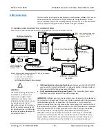
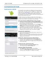
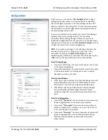
At this point, you can click the
“I/O Config/Test”
tab to begin
configuring the transmitter, or to optionally test its operation.
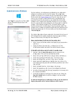
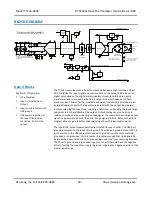
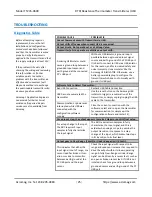
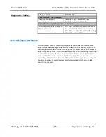
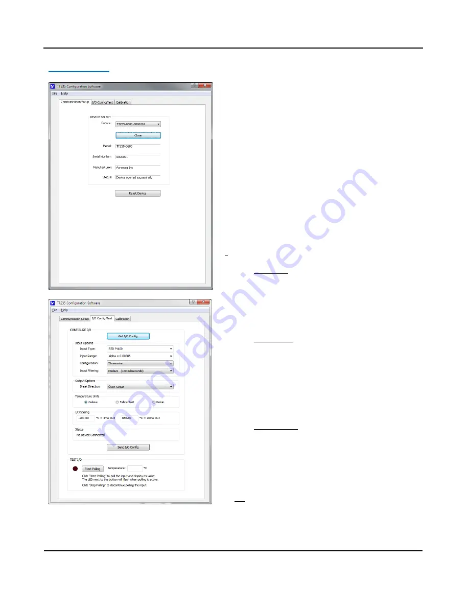
The I/O Config/Test window is the second image shown at left.
When you click the “I/O Config/Test” tab, the software retrieves
the transmitter’s current configuration and displ
ays it similar to
the second image shown at left.
If you are connected to a transmitter, the initial I/O Config page
represents the current configuration of the connected
transmitter before making changes. Otherwise, if you have
loaded the configuration from a saved a file, or if you have made
changes to any fields, you can click the
[Get I/O Config]
button to
retrieve the transmitter’s current configuration.
NOTE:
If you make any changes to the selections indicated, the
only way to preserve your changes is to write them to the
transmitter by clicking the
[Send I/O Config]
button after
completing your selections, or save them to a file by opening the
“
File
” menu in the upper left
-hand corner of the window.
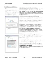
Select the Input Type...
•
If you select a RTD type, the output will be linear with respect
to the sensor temperature.
•
If you select Resistance
,
the output will be linear with respect
to the input resistance, not temperature, and no special
linearization will be performed.
Select the Input Range...
•
If RTD Input Type is selected, then the Input Range menu will
display RTD alpha values. Refer to “RT
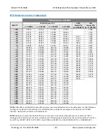
D Resistance versus
Temperature
” section
for an explanation of alpha value.
•
If Resistance Input Type is selected, then the Input Range
menu will display resistance ranges. Select the lowest
resistance range that can support the input resistance full-
scale.
Select the Configuration...
•
If you select
“
Four-w
ire”
, the sensor lead-wire resistance will
have a negligible effect on the sensor measurement.
•
If you select
“
Three-
wire”
, the sensor lead-wire resistance
will be compensated for, as long as the [+] and [L] leads are
of the same length, size, and type.
•
If you select
“Two
-
wire”
, the sensor lead-wire resistance will
not be compensated for, and the total resistance of the ±
lead-wires will contribute a positive shift in the sensor
measurement.

