background image

Model TT235-0600


RTD/Resistance Thermometer Transmitter w/USB 


Acromag, Inc. Tel: 248-295-0880  


  - 34 -     

http://www.acromag.com  

[

 34 

]


https://www.acromag.com 


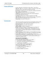
Enclosure & Physical 


General purpose plastic enclosure for mounting on 35mm “T

-

type” DIN rail.


Dimensions

:  Width = 12.5mm (0.5 inches), Length = 114.5mm (4.51 inches), Depth = 

99.0mm (3.90 inches).  Refer to Mechanical Dimensions drawing. 

I/O Connectors:

  Removable plug-in type terminal blocks rated for 12A/250V; AWG 

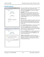
#26-12, stranded or solid copper wire. 

Program Connector:  

USB Mini B-type, 5-pin.  See USB Interface. 

Case Material:

  Self-extinguishing polyamide, UL94 V-0 rated, color light gray.  

General purpose NEMA Type 1 enclosure. 

Circuit Board:

  Military grade fire-retardant epoxy glass per IPC-4101/98. 

DIN-Rail Mounting:  

Transmitter is normally mounted to 35x15mm, T-type DIN rails.  

Refer to the DIN Rail Mounting & Removal section for more details. 

Shipping Weight:  

0.5 pounds (0.22 Kg) packed. 


Environmental 


These limits represent the minimum requirements of the applicable standard, but this 
product has typically been tested to comply with higher standards in some cases. 

Operating Temperature:  

-40

C to +80

C (-40

F to +176

F). 

Storage Temperature:  

-40

C to +85

C (-40

F to +185

F). 

Relative Humidity:

  5 to 95%, non-condensing. 

Isolation:  

Input/USB, output/power circuits are isolated from each other for 

common-mode voltages up to 250VAC, or 354V DC off DC power ground, on a 
continuous basis (will withstand 1500VAC dielectric strength test for one minute 
without breakdown). Complies with test requirements of ANSI/ISA-82.01-1988 for 
voltage rating specified. 

Installation Category:

  Suitable for installation in a Pollution Degree 2 environment 

with an Installation Category (Over-voltage Category) II rating per IEC 1010-1 (1990). 

Shock & Vibration Immunity: 

 Conforms to: IEC 60068-2-6: 10-500 Hz, 4G, 2 

Hours/axis, for sinusoidal vibration; IEC 60068-2-64: 10-500 Hz, 4G-rms, 2 Hours/axis, 
for random vibration, and IEC 60068-2-27:  25G, 11ms half-sine, 18 shocks at 6 
orientations, for mechanical shock. 

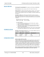
Electromagnetic Compatibility (EMC)  
Minimum Immunity per BS EN 61000-6-1 

1.


Electrostatic Discharge Immunity (ESD), per IEC 61000-4-2 

2.


Radiated Field Immunity (RFI), per IEC 61000-4-3 

3.


Electrical Fast Transient Immunity (EFT), per IEC 61000-4-4 

4.


Surge Immunity, per IEC 61000-4-5 

5.


Conducted RF Immunity (CRFI), per IEC 61000-4-6 

Class B Product with Emissions per BS EN 61000-6-3 

1.


Enclosure Port, per CISPR 16 

2.


Low Voltage AC Mains Port, per CISPR 14, 16 

3.


DC Power Port, per CISPR 16 

4.


Telecom / Network Port, per CISPR 22 


Содержание TT235-0600

Страница 1: ...D Resistance Input 4 20mA Output USER S MANUAL ACROMAG INCORPORATED 30765 South Wixom Road Wixom MI 48393 2417 U S A Copyright 2018 Acromag Inc Printed in the USA Data and specifications are subject to change without notice Tel 248 295 0880 Fax 248 624 9234 email sales acromag com 8500995M ...

Страница 2: ...L CONNECTIONS 6 Sensor Input Connections 7 Output Power Connections 10 Earth Ground Connections 12 USB Connections 13 CONFIGURATION SOFTWARE 14 Quick Overview Android 14 Quick Overview Windows 15 OPERATION STEP BY STEP 17 Connections 17 Configuration 19 Calibration Optional 21 RTD Resistance versus Temperature 23 BLOCK DIAGRAM 24 How It Works 24 TROUBLESHOOTING 25 Diagnostics Table 25 Service Repa...

Страница 3: ...es in designing any type of control or monitoring system This is especially important where economic property loss or human life is involved It is important that the user employ satisfactory overall system design It is agreed between the Buyer and Acromag that this is the Buyer s responsibility The information of this manual may change without notice Acromag Inc makes no warranty of any kind with ...

Страница 4: ...scale lead break burnout detection RTD inputs are linearized with respect to temperature Supports Celsius Fahrenheit and Kelvin temperature units Adjustable input range and selectable output ranges Input and output circuits are fully isolated from each other Convenient two wire loop power with non polarized output connections Normal or reverse acting output Namur compliant loop current Variable in...

Страница 5: ...r 50VAC DIN Rail Mounting Removal Refer to the following figure for mounting and removing a module from the DIN rail Mounting A spring loaded DIN clip is located on the input side bottom The rounded edge of the output side bottom allows the module to tilt upward so that it may be lifted from the rail when prying the spring clip back with a screwdriver To attach a module to T type DIN rail angle th...

Страница 6: ... known to be non hazardous before servicing replacing the unit and before installing Wire terminals can accommodate 14 26 AWG 2 08 0 13mm2 solid or stranded wire with a minimum temperature rating of 85o C Input wiring may be shielded or unshielded type Ideally output wires should be twisted pair Terminals are pluggable and can be removed from their sockets by prying outward from the top with a fla...

Страница 7: ...in the connection drawing below Transmitter input signal is isolated from output Three wire input sensors require jumper For three wire sensors including resistive elements a copper jumper wire must be connected between input pins 1 and 4 and H Two wire input sensors require jumpers For a two wire sensor including resistive elements a copper jumper wire must be connected between input pins 4 and 5...

Страница 8: ...CLIP TB3 OUTPUT TB1 INPUT TB2 INPUT 2 1 H 4 3 L TB4 COMMON 1 2 3 4 L H MODEL TT235 0600 INPUT SENSOR WIRING SEE FOLLOWING PAGE FOR INPUT SENSOR WIRING DETAILS INPUT SENSOR SHIELDED CABLE SHIELDED CABLE IS RECOMMENDED FOR BEST RESULTS GROUND THE CABLE SHIELD AT THE END OF THE CABLE CLOSEST TO THE GREATEST POTENTIAL SOURCE OF DISTURBANCE USUALLY THE SENSOR END NOTE SHIELDED CABLE GROUND OPTIONAL SHI...

Страница 9: ...GIBLE EFFECT ON THE RTD MEASUREMENT WHEN USING A 4 WIRE CONFIGURATION NOTE LEAD WIRE RESISTANCE THE LEAD WIRE RESISTANCE WILL BE COMPENSATED FOR AS LONG AS THE RESISTANCE OF THE AND L LEADS ARE MATCHED ANY UNBALANCE WILL CONTRIBUTE A SHIFT IN THE RTD MEASUREMENT NOTE LEAD WIRE RESISTANCE THE RESISTANCE OF THE AND LEAD WIRES WILL CONTRIBUTE A POSITIVE SHIFT IN THE RTD MEASUREMENT THE DEGREE AMOUNT ...

Страница 10: ...in load resistance has negligible effect on output accuracy as long as the loop supply voltage is set accordingly Note the traditional placement of earth ground in the current loop The transmitter output minus varies off this ground by the voltage drop in the load resistance and lead wire The traditional loop powered sinking output connections are shown above Shielded twisted pair wiring is often ...

Страница 11: ...he load can reduce this ripple further For large 60Hz supply ripple connect an external 1uF or larger capacitor directly across the load to reduce excessive ripple For sensitive applications with high speed acquisition at the load high frequency noise may be reduced significantly by placing a 0 1uF capacitor directly across the load as close to the load as possible TIP Inductive Loads If the two w...

Страница 12: ...ally applied at the output loop power minus terminal and in common with the loop load or loop receiver minus The Type II transmitter output terminals have a floating connection relative to earth ground and their potential varies with the voltage drop in the load and connection wire Respect the traditional position of earth ground in a two wire current loop and avoid inadvertent connections to eart...

Страница 13: ...d The potential of the transmitter s current output pin output minus relative to earth ground will vary according to the load current and load resistance net IR drop Without isolation this IR drop would drive a potential difference between the normally grounded current loop and the grounded USB connection at the PC causing a ground loop that would inhibit setup and calibration and may even damage ...

Страница 14: ... Diagram button and select the desired model Swipe left or right to view more diagrams No connection is required to view the diagrams Android requires user permission to access external hardware If the Device List displays No Device Permission select this device and when prompted to give permission to access the USB device tap OK Configuration Tab CONFIGURE I O Once connected the app will automati...

Страница 15: ...t left Configuration information is divided across three pages as follows Communication Setup I O Config Test and Calibration Communication Setup First Connect to Transmitter Here Select from connected transmitters and Open Close communication with them Display the Model Serial Number and Manufacturer of the connected transmitter and report the status of communication I O Config Test Configure and...

Страница 16: ...ly click the respective Cal Instructions button and follow the prompts Input Before calibration first select the Input Type to calibrate from the I O Config page and be sure to click the Send I O Config button On the Calibration page click the Input Cal Instructions button to begin input calibration When you click Zero Scale or Full Scale of the Input Calibration section you will be prompted to ap...

Страница 17: ...alibrate the transmitter You can connect a current meter in series in this loop to read the loop current directly not recommended Alternatively you could simply connect a voltmeter across a series connected precision load resistor in the loop and accurately read the output current as a function of the IR voltage drop produced in this resistor recommended In any case be sure to power the loop with ...

Страница 18: ...ond window at left If you happen to be connected to more than one transmitter via a USB hub you can use the device scroll field to select another transmitter using the serial information suffix of the model number to discern one transmitter from another Select a transmitter from the drop down menu When you click on a transmitter name from the drop down menu the software will automatically attempt ...

Страница 19: ...after completing your selections or save them to a file by opening the File menu in the upper left hand corner of the window Select the Input Type If you select a RTD type the output will be linear with respect to the sensor temperature If you select Resistance the output will be linear with respect to the input resistance not temperature and no special linearization will be performed Select the I...

Страница 20: ...tware You may select Celsius Fahrenheit or Kelvin Enter the I O Scaling values You may rescale the input range to use only a portion of the input range to drive the output if desired Be careful not to reduce the input range too much as resolution will be proportionally diminished and noise error magnified In the corresponding I O Scaling field enter the input signal minimum zero value to correspon...

Страница 21: ... selected Input Type on the I O Config page is the desired sensor input type you intend to calibrate Additionally make sure you write your selections to the transmitter by clicking the Send I O Config button Click the Input Cal Instructions button to begin input calibration and enable the Input Zero Scale and Full Scale buttons Click the Input Zero Scale button of the Calibration Input section and...

Страница 22: ...he transmitter If your output acts erratic or appears imprecise you may need to repeat input or output calibration being very careful to take accurate measurements and input correct signal levels If you are measuring a voltage across a load resistance make sure that you use the exact resistance when calculating the load current being measured Also when rescaling to a smaller sub range make sure th...

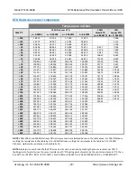
Страница 23: ...707 135 160 135 249 135 333 191 64 12 511 100 138 506 139 007 139 107 139 200 200 64 12 897 150 157 325 158 066 158 222 158 360 248 95 14 828 200 175 856 176 828 177 044 177 226 303 46 16 776 250 194 098 195 294 195 574 195 799 366 53 18 725 300 212 052 213 463 213 811 214 079 439 44 350 229 716 231 336 231 756 232 065 400 247 092 248 912 249 409 249 758 450 264 179 266 192 266 769 267 157 500 280...

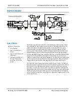
Страница 24: ...iagram above to gain a better understanding of how this transmitter works The input USB output power circuits are isolated from each other The USB port ground is common to the input circuit ground The USB port ground of most PC s is also common to the USB cable shield and earth ground Input sensors could be grounded or ungrounded For this reason it is recommended that USB signals be isolated when ...

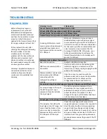
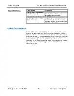
Страница 25: ...Otherwise use a battery powered laptop to configure the transmitter which does not normally earth ground its USB port Software Fails to Detect Transmitter Bad USB Connection Recheck USB Cable Connection USB has not enumerated the transmitter Use the reset button on the Acromag USB isolator to trigger re enumeration of the transmitter or simply unplug re plug the USB cable to the transmitter Commun...

Страница 26: ...ections for wiring sensors to the transmitter Service Repair Assistance This transmitter contains solid state components and requires no maintenance except for periodic cleaning and transmitter calibration and verification zero and full scale Its enclosure is not meant to be opened for access and can be damaged easily if snapped apart It is highly recommended that a non functioning transmitter be ...

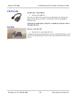
Страница 27: ...m the transmitter USB Isolator USB Isolator Order USB ISOLATOR USB Signal Isolator USB A B Cable 4001 112 Instructions 8500 900 This kit contains a USB isolator and a 1 meter USB A B cable for connection to a PC This isolator and cable are also included in TTC SIP see above USB A B Cable USB A B Cable Order 4001 112 USB A B Cable 4001 112 This is a 1 meter USB A B replacement cable for connection ...

Страница 28: ...etween the USB A mini B Cable and a mobile phone or tablet It is required to use the Acromag Agility Config Tool App Note that the Acromag Agility Config Tool is available free of charge online at the Google Play store End Stops End Stops Order 1027 222 End Stops for 35 mm DIN Rails 1027 222 For hazardous location installations Class I Division 2 or ATEX IECEx Zone 2 it must use two end stops Acro...

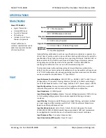
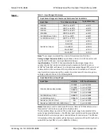
Страница 29: ...an be mounted on standard 35mm T Type DIN rail Input Input Reference Test Conditions 100Ω Pt RTD α 0 00385 200 C to 850 C input Configuration Three wire Filtering Medium Output 4 to 20mA ascending R Load 250Ω Break detection Over range Ambient 25 C Power supply 24VDC Input Configuration Four wire lead wire has negligible effect three wire with lead wire compensation and two wire without lead wire ...

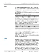
Страница 30: ... Gain 1 for all input types except Copper RTD which is set to Gain 16 Rin is the resistance of the input the sensor An indication of nominal input resolution is expressed as the number of parts between the input range low and high endpoints shown in the following table Input Resolution per Input Type Input Type α Alpha1 ADC Input Resolution Pt 100Ω 200Ω 500Ω 1000Ω 0 00385 1 part in 24425 0 00390 1...

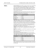
Страница 31: ...60Hz Rejection per Input Filter None Low Medium High 17dB 34dB 80dB 80dB Lead Wire Compensation Requires balanced and L sensor leads same size length type and only used with three wire configuration Lead Wire Resistance Effect Four wire configuration Less than 0 001 C per Ω of unbalance typical Three wire and two wire configurations 3 5 C per Ω of unbalance typical Pt100 1 4 C per Ω of unbalance t...

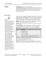
Страница 32: ...6V even with a shorted load The supply voltage level must be chosen to provide a minimum of full scale current to the load 0 020 R typical plus 11V minimum to the transmitter terminals plus any line drop Ideally the supply should drive over scale current levels up to 24mA into load Reverse polarity protection is inherent as output terminals are not polarized The output polarity labels on the enclo...

Страница 33: ...ry powered laptop could be used to connect to the transmitter as the laptop does not normally connect to earth ground Transmitter includes a USB socket for temporary connection to a PC or laptop for the purpose of setup and reconfiguration USB isolation is required when connected to a grounded input sensor see IMPORTANT note on the left During reconfiguration and calibration the transmitter receiv...

Страница 34: ...emperature 40 C to 85 C 40 F to 185 F Relative Humidity 5 to 95 non condensing Isolation Input USB output power circuits are isolated from each other for common mode voltages up to 250VAC or 354V DC off DC power ground on a continuous basis will withstand 1500VAC dielectric strength test for one minute without breakdown Complies with test requirements of ANSI ISA 82 01 1988 for voltage rating spec...

Страница 35: ... protection not less than IP 54 and only accessible with the use of a tool in accordance with EN IEC 60079 0 3 Transient protection shall be provided that is set at a level not exceeding 140 of the peak rated voltage value at the supply terminals to the equipment Reliability Prediction MTBF Mean Time Between Failure MTBF in hours using MIL HDBK 217F FN2 Per MIL HDBK 217 Ground Benign Controlled GB...

Страница 36: ...RP JMO ARP Added cULus Mark to this model removed pending Updated Configuration section Added instructions for new Input Ranges Updated Input Range table Added resistance Input Ranges 25 900 2250 and 4500 Ohms Updated accuracy Updated Input Range table Note 1 Low input resistance doesn t trigger break detect when Resistance Input Type selected Updated Input Resolution table Added data for new Inpu...

Отзывы: