Model TT235-0600
RTD/Resistance Thermometer Transmitter w/USB
Acromag, Inc. Tel: 248-295-0880
- 20 -
http://www.acromag.com
[
20
]
https://www.acromag.com
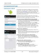
Configuration...
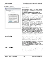
HELP:
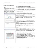
You can press
[F1]
for Help on a selected or
highlighted field or control. You can also click the
[?]
button in the upper-right hand corner of the window
and click on a field or control to get a Help message
pertaining to the item you clicked on.
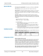
NOTE:
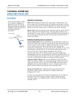
Under-range (3.5mA) and over-range (24mA)
capability is built into the output range by design.
See Output Specifications for more detail.
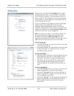
Select the Input Filtering...
Select the level of digital filtering to apply to the input channel as
“
None
”
,
“Low”
,
“Medium”
, or
“High”
. The respective I/O
response times are indicated in parenthesis next to the filter
selection. Note that higher filter levels results in lower average
noise, but with slower I/O response times.
Select the Break Direction...
Upon sensor burnout or a broken sensor lead, you can select
“Under
-
range”
to send the output to its under-range limit, or
“Over
-
range”
to send the output to the over-range limit. Note
that outputs can be reverse acting, but in the case, under-range
and over-range remain normal. Under-range and over-range limits
are outside the nominal output range selected.
Select the Temperature Units...
Select the temperature units to use in the Configuration Software.
You may select Celsius, Fahrenheit, or Kelvin.
Enter the I/O Scaling values...
You may rescale the input range to use only a portion of the input
range to drive the output if desired. Be careful not to reduce the
input range too much, as resolution will be proportionally
diminished and noise/error magnified.
In the corresponding I/O Scaling field, enter the input signal
minimum/zero value to correspond to the output range Zero-
Scale value (4mA). Also set the input range Full-Scale (20mA). You
can optionally swap I/O Scaling values to configure a reverse
acting output response if desired. Note: Under-range (3.5mA) and
over-range (24mA) is built into the output range by design.
If the I/O Scaling Zero-Scale and Full-Scale points are chosen too
close together, performance will be degraded.
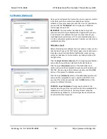
Submit I/O Configurations
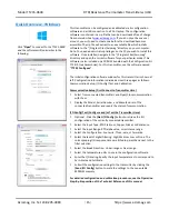
Once you have made your configuration selections, click the
[Send
I/O Config]
button to write them to the transmitter. You can read
the status of your sent message in the
“Status” field. Alternately,
you could click
“
F
ile”
in the upper left-hand corner to save the
configuration settings to a file on your PC for later reference.
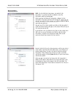
At this point, you can test the transmitter’s operation by clicking
on the
[Start Polling]
button of the TEST I/O Section of the page to
trigger the software to periodically read the input and display its
value in the field to the right of the polling toggle button. Note the
simulated lamp next to the button flashes each time the input is
sampled. Click
[Stop Polling]
to stop polling the input.

