Model TT235-0600
RTD/Resistance Thermometer Transmitter w/USB
Acromag, Inc. Tel: 248-295-0880
- 12 -
http://www.acromag.com
[
12
]
https://www.acromag.com
Output/Power
Connections...
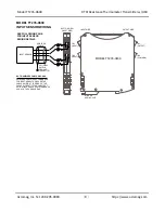
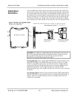
This model includes two extra terminal connections at TB4 marked “C”, which
provide a convenient wiring point for a “sourcing” wiring variation as shown below.
Internally, these two terminals are connected in common with each other and do
not connect to the internal circuit. Use of these terminals in the wiring scheme
allows external power to be connected local to the transmitter and form a
“sourcing” output entity from this “sinking” output as shown.
Earth Ground Connections
The transmitter housing is plastic and does not require an earth ground connection,
except where the optional input cable shield is terminated on the transmitter If the
transmitter is mounted in a metal enclosure, an earth ground wire connection to
the metal
enclosure’s
ground terminal (green screw) is usually required using
suitable wire per applicable codes. See the Electrical Connections Drawing for
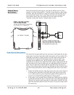
Output/Power connections and note the traditional position of earth ground for the
two-wire output current loop. Earth ground is normally applied at the output loop
power minus terminal and in common with the loop load or loop receiver minus.
The Type II transmitter output terminals have a floating connection relative to earth
ground and their potential varies with the voltage drop in the load and connection
wire.
Respect the traditional position of earth ground in a two-wire current loop and
avoid inadvertent connections to earth ground at other points in the output
circuit, which would drive ground loops and negatively affect operation. The
input circuit is isolated and may additionally be earth grounded.
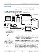
A USB isolator is recommended when configuring or calibrating a transmitter to
avoid the ground loop that occurs if the input sensor is also earth grounded (PC
USB ports are commonly earth grounded and make contact with both the USB
signal and shield ground which is held in common to the input circuit ground of
the transmitter).
R
I
I
LOAD
OPTIONAL COMMON CONNECTIONS
WITH LOCAL EXTERNAL 3-WIRE POWER
FORM A SOURCING OUTPUT RELATIVE
TO THE REMOTE SINKING LOAD.
6
5
–
+
I
I
I
I
8
7
C
OPTIONAL "SOURCING" OUTPUT CONNECTIONS
WITH POWER LOCAL TO TRANSMITTER
C
ANY MODEL TT2XX-0600
5
6
–
+
8
7
C
C
INPUT SIDE
OUTPUT SIDE
TOP VIEW
(OUTPUT SIDE)
TB3
(OUTPUT)
TB1
(INPUT)
TB2
(INPUT)
TB4
(COMMON)
MODEL TT2XX-0600 OPTIONAL
OUTPUT/POWER WIRING
I
REMOTE
RECEIVER/LOAD
TWISTED PAIR
LOCAL 24VDC
POWER SUPPLY
24VDC
LOOP
LOOP


