AXM-
A75 User’s Manual
Multifunction I/O Mezzanine Board
_____________________________________________________________________________________
- 27 -
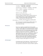
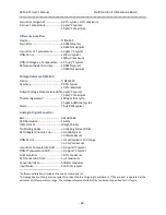
Power Requirements
+3.3 Volts (
5%) ............................ 39 mA typical
50 mA maximum
+5 Volts (
5%) ............................... 54 mA typical
65 mA maximum
+12V (
5%) .................................... 103 mA typical
115 mA maximum
-12V (
5%)..................................... 92 mA typical
115 mA maximum
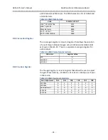
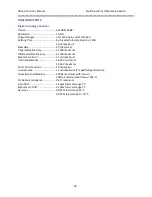
ANALOG INPUTS
Device ............................................ ADI AD7686
Input Channels .............................. 16 differential
Input Signal Type ........................... Voltage (Non-isolated)
Input Ranges: ................................ ±10.24, ±5.12, ±2.56 and ±1.28 V
Input Overvoltage Protection ....... ±25 V with power on
Input Resistance ............................ 5.300 G
, typical differential
Input Bias Current ......................... 5 nA typical
40 nA maximum
Common Mode Rejection Ratio ... 98 dB typical (60 Hz)
Input Channel to Input Channel Rejection Ratio
1
41 dB typical (100 kHz)
Output Channel to Input Channel Rejection Ratio
2
85 dB typical (1 kHz)
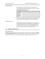
Accuracy ........................................
Gain % Full Scale @ 25°C
% Full Scale 0
–
70°C
1
0.011
0.026
2
0.013
0.029
4
0.015
0.033
8
0.018
0.040
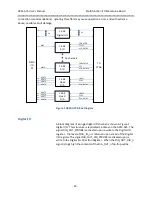
Programmable Gain Instrumentation Amplifier
Device ............................................ ADI AD8251
PGA Linearity Error........................
0.005
maximum (3.27 LSB)
Offset Error RTI
1.0 mV typical,
2.5 mV maximum
Offset vs. Temperature .................
(0.6 + 1.5/G) µV/°C typical (G=1,2,4,8)
(1.2 + 5/G) µV/°C maximum
1
Input channel to input channel rejection ratio was measured with a 100 KHz 1V pk-pk sine wave input on an
adjacent channel.
2
The output channel to input channel rejection ratio was measured with all output channels driving a 10k ohm
load outputting a 1 kHz 20 V pk-pk sine wave. Load resistors were located on a termination panel connected to a 2
meter cable.


