AXM-
A75 User’s Manual
Multifunction I/O Mezzanine Board
_____________________________________________________________________________________
- 18 -
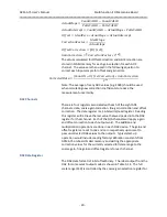
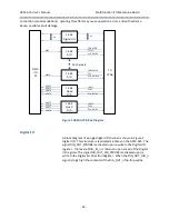
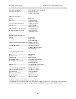
selected full scale range to the gain and offset registers for each
channel.
ADC Data Format
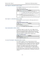
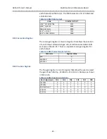
The output from the ADC is offset binary format as shown in Table
3-12. The full scale range (±10.24, ±5.12, ±2.56, ±1.28) is controlled
by the gain selection in the control register. See Table 3-4.
Table 3-12 ADC Data Format
DESCRIPTION
DIGITAL OUTPUT
+ Full Scale
FFFF
Midscale (zero)
8000
1 LSB Below Midscale
7FFF
- Full Scale
0000
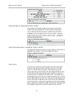
ADC Offset Register
The offset register contains a
16 bit two’s complement value
that is
added to the value output from the ADC to correct offset errors.
There is a separate offset register for each channel.
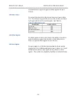
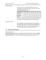
ADC Gain Register
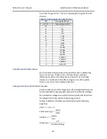
The gain register is a 17 bit fixed point positive fractional number
ranging from 0 to 1.999984 weighted as shown in Table 3-13. The 17
bit fixed point number is least significant bit justified in a 32 bit
register. This number is multiplied by the offset corrected ADC value


