


AXM-
A75 User’s Manual
Multifunction I/O Mezzanine Board
_____________________________________________________________________________________
- 15 -
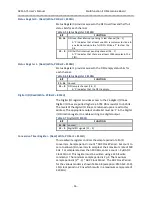
BIT
FUNCTION
30- 16
Reserved for base board
15 - 13
AXM Identification bits (Read Only)
AXM-EDK
“001”
AXM-A75
“
011
”
12 - 2
Reserved for base board
1
FIFO overflow interrupt pending
0
FIFO half full interrupt pending
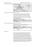
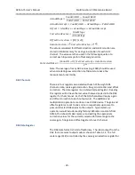
Control Register - (Read/Write, P 8100H)
The control register is used to enable interrupts, control amplifier
gain, control the FLASH chip select signal, and start/stop the A/D
converter for each channel. See Table 3-4 for a description of each of
the register bits.
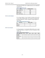
Table 3-4 Control Register 8100H
BIT
FUNCTION
31
FIFO overflow interrupt enable
30
FIFO half full interrupt enable
29
–
28
Amplifier Gain
“00” Gain
1, full scale input range ± 10.24 Volts
“01” Gain 2, full scale input range
± 5.12 Volts
“10” Gain 4, full scale input range
± 2.56 Volts
“11” Gain 8, full scale input range
± 1.28 Volts
27
FLASH Select
–
This bit is connected directly to
the “select”
input of the serial FLASH device.
26
LDAC
–
transfer DAC data from data registers to output
registers, all channels (write only, read zero)
25
CLR
–
clear DAC data registers to 0x00 all channels, (write only,
read zero)
24
–
16
unused
15
–
0
Convert channel [16 .. 1]
–
each channel can be individually
controlled
0
–
channel stopped
1
–
enable continuous conversion


