


AXM-
A75 User’s Manual
Multifunction I/O Mezzanine Board
_____________________________________________________________________________________
- 14 -
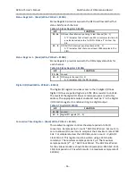
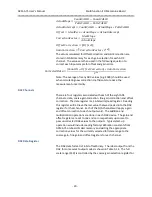
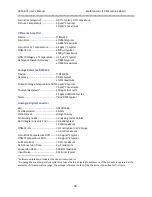
Addr
D31 D16
D15 D00
Addr
.
0187
2.56 Volt Range Channel 16 Gain
0184
018B
1.28 Volt Range Channel 1 Offset
0188
018F
1.28 Volt Range Channel 2 Offset
018C
0193
1.28 Volt Range Channel 3 Offset
0190
.
.
.
01C7
1.28 Volt Range Channel 16 Offset
01C4
01CB
1.28 Volt Range Channel 1 Gain
01C8
01CF
1.28 Volt Range Channel 2 Gain
01CC
01D3
1.28 Volt Range Channel 3 Gain
01D0
.
.
.
0207
1.28 Volt Range Channel 16 Gain
0204
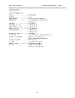
020B
DAC Offset Channel 1
0208
020F
DAC Offset Channel 2
020C
0213
DAC Offset Channel 3
0210
.
.
.
0227
DAC Offset Channel 8
0224
0247
Unused
0228
024B
DAC Gain Channel 1
0248
024F
DAC Gain Channel 2
024C
0253
DAC Gain Channel 3
0250
.
.
.
0267
DAC Gain Channel 8
0264
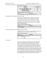
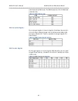
Board Status and Reset Register (Read/Write, P 8000H)
This read/write register is used to issue a software reset, view and
clear pending interrupts, and to identify the attached AXM module. It
may also provide other functions that are defined by the base board.
Writing a “1” to bit 31 of this register will
cause a software reset
affecting both the PMC base board and the majority of AXM-A75
registers. Bits 15 to 13 are used for AXM identification code.
Read
of this register reflects the interrupt pending status. Read of a
“1”
in bits 1 or 0 indicates that an interrupt is pending for the
corresponding interrupt.
Table 3-3 Board Status and Reset Register 8000H
BIT
FUNCTION
31
Software Reset (Write Only)


