INDUSTRIAL I/O PACK SERIES APCe8650
PCI BUS CARRIER BOARD
Acromag, Inc. Tel: 248-295-0310
- 8 -
www.acromag.com
cartons and packing material be saved for future use in the event the product
must be shipped.
This board is physically protected with packing material and electrically
protected with an anti static bag during shipment. It is recommended that
the board be visually inspected for evidence of mishandling prior to applying
power.
The board utilizes static sensitive components and should only be handled at
a static-safe workstation.
CARD CAGE CONSIDERATIONS
Refer to the specifications for loading and power requirements. Be sure that
the system power supplies are able to accommodate the power requirements
of the carrier board, plus the installed IP modules, within the voltage
tolerances specified.
IMPORTANT: Adequate air circulation must be provided to prevent a temperature rise above the maximum
operating temperature.
The lack of air circulation within the computer chassis is a cause for some
concern. Most, if not all, computer chassis do not provide a fan for cooling of
add-in boards. The dense packing of the IP modules to the carrier board
alone results in elevated IP module and carrier board temperatures, and the
restricted air flow within the chassis aggravates this problem. Adequate air
circulation must be provided to prevent a temperature rise above the
maximum operating temperature and to prolong the life of the electronics. If
the installation is in an industrial environment and the board is exposed to
environmental air, careful consideration should be given to air-filtering.
Board Configuration
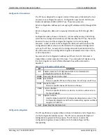
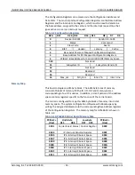
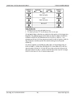
The carrier board is plug-and-play compatible and, as such, its board
addresses are automatically assigned by the system auto-configuration
routine upon power-up. The base address of the carrier board’s configuration
registers in memory space and I/O space is assigned. In addition, the base
addresses of the IP modules and carrier board registers are assigned in 32-bit
memory space.
Power should be removed from the board when changing jumper
configurations or when installing IP modules, cables, termination panels, and
field wiring. Refer to Mechanical Assembly Drawing 4502-148 and your IP
module documentation for specific configuration and assembly instructions.
See diagram 4502-135 located in the drawings portion of this manual for
jumper location and settings. The jumper must be present in one of the two
configurations for proper board operation. Factory default is memory space
disabled.


