INDUSTRIAL I/O PACK SERIES APCe8650
PCI BUS CARRIER BOARD
Acromag, Inc. Tel: 248-295-0310
- 22 -
www.acromag.com
Carrier Board Registers
The carrier board registers (presented in section 3) are implemented in the
logic of the carrier board’s FPGA. An outline of the functions provided by the
carrier board registers includes:
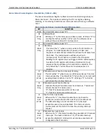
Selecting either an 8MHz or 32MHz clock for each IP module in the
Clock
Control Register
.
Monitoring the error signal received from each IP module is possible via the
IP
Error Bit
.
Enabling of PCI bus interrupt requests from each IP module is possible via the
IP Module Interrupt Enable Bit
.
Enabling of interrupt generation upon an IP module access time out is
implemented via the
Time Out Interrupt Enable Bit.
Monitoring an IP module access time out is possible via the
IP Module Access
Time Out Status Bit.
Identify pending interrupts via the carrier’s
IP Module Interrupt Pending
Bit
.
Pending interrupts can be individually monitored via the
IP Module Interrupt
Pending register
.
A non-volatile ID can be written to and read from a serial FLASH memory by
accessing the ID register.
IP Logic Interface
The IP logic interface is also implemented in the logic of the carrier board’s
FPGA. The carrier board implements ANSI/VITA 4 1995 Industrial I/O Pack
logic interface specification and includes four IP logic interfaces. The PCIe bus
is linked to the address and data of the IP bus interface. This link is
implemented and controlled by the carrier board’s FPGA.
The PCIe bus to IP bus interface allows a PCIe bus master to:
Access up to 64 ID Space bytes for IP module identification via 8-bit or 16-bit
data transfers using PCIe bus.
Access up to 128 I/O Space bytes of IP data via 8-bit or 16-bit data transfers.
Access up to 8M byes of IP Memory Space data via 8-bit or 16-bit data
transfers.
Access IP module interrupt space via 8-bit or 16-bit PCI bus data transfers.
Respond to two IP module interrupt requests per IP module.
When an IP module places data on the bus, for all data read cycles, any
undriven data lines are read by the PCI bus as high because of pull-up
resisters on the carrier board’s data bus.


