INDUSTRIAL I/O PACK SERIES APCe8650
PCI BUS CARRIER BOARD
Acromag, Inc. Tel: 248-295-0310
- 19 -
www.acromag.com
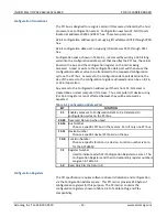
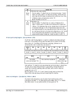
MSB
D15 -- D4
D3
D2
D1
LSB
D0
Not Used
IP D CLK
IP C CLK
IP B CLK
IP A CLK
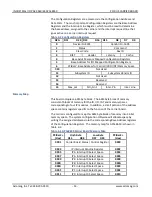
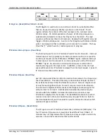
ID Register - (Read/Write, P 01AH)
The ID Register is used to store and retrieve a 16 bit non-volatile identifier
that can be used to uniquely identify a particular carrier board. The ID
register reflects the contents of the first two bytes of an on-board serial
FLASH memory. On initial application of power, a FLASH read sequence is
automatically initiated to retrieve the ID bytes from the FLASH. The read
sequence will take less than 5 microseconds. Reading the ID register does not
trigger a FLASH read sequence. A write to the ID register will initiate a FLASH
write / read sequence that could take up to 3 seconds to complete. The busy
bit will be “1” while the write / read sequence is in progress.
IP Module Interrupt Space - (Read Only)
The Interrupt space for each IP module is fixed at two 16-bit words. Interrupt
0 select space is read, typically by an interrupt service routine, to respond to
an interrupt request via the IP Module’s INTREQ0* signal. Likewise interrupt
1 select space is read to respond to an interrupt request via the IP Module’s
INTREQ1* signal. An access to an interrupt select space results in the IP
module serving up an interrupt vector. In addition, access to the interrupt
space will cause some IP modules to release their interrupt request. See each
IP module’s User Manual for details.
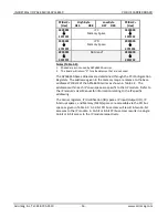
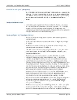
IP Module ID Space- (Read Only)
Each IP contains identification (ID) information that resides in the ID space per
the IP specification. This area of memory contains either 32 bytes (Format I
ID) or 64 bytes (Format II ID) of information, at most. Format I requires read
of only the least significant byte. Format II requires read of a 16-bit value.
The carrier will implement 16-bit reads to the ID space to allow support for
either Format I or Format II. Both fixed and variable information may be
present within the ID ROM. Variable information may include unique
information required for the module. The identification Section for each IP
module is located in the carrier board memory map per Table 3-3. Refer to
the documentation of your IP module for specific information about each IP
module’s ID Space contents.
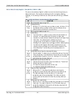
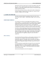
IP Module I/O Space - (Read/Write)
The I/O space on each IP module is fixed at 64, 16-bit words (128 bytes). The
four IP module I/O spaces are accessible at fixed offsets from PCIBar2. IP
modules may not fully decode their I/O space and may use byte or word only
accesses. See each IP module’s User Manual for details.


