INDUSTRIAL I/O PACK SERIES APCe8650
PCI BUS CARRIER BOARD
Acromag, Inc. Tel: 248-295-0310
- 18 -
www.acromag.com
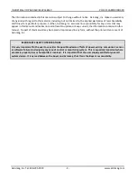
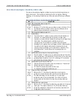
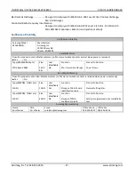
BIT
FUNCTION
1
Read
Only
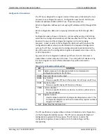
IP Module Interrupt Pending
This bit will be "1" when there is an interrupt pending. This bit
will be "0" when there is no interrupt pending. Polling this bit
will reflect the IP Module’s pending interrupt status, even if the
IP Module Interrupt Enable bit is set to "0".
Reset condition: Set to "0".
0
Read
Only
IP Module Error
This bit will be "1" when there is an active IP Module Error
signal. This bit will be "0" when all IP module Error signals are
inactive. This bit allows the user to monitor the Error signals of
IP modules A through D. The IP specification states that the
error signals indicate a non-recoverable error from the IP (such
as a component failure or hard-wired configuration error). Refer
to your IP specific documentation to see if the error signal is
supported and what it indicates. Reset condition: Set to "0".
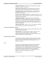
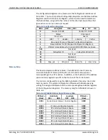
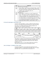
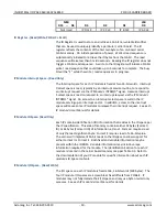
IP Interrupt Pending Register - (Read, P 02H)
The IP Interrupt Pending Register is used to individually identify pending IP
interrupts or a pending carrier generated interrupt as a result of IP module
access time out. If multiple IP interrupts are pending, software must
determine the order in which they are serviced.
MSB
D7
D6
D5
D4
D3
D2
D1
LSB
D0
IP D Int1
Pend
IP D Int0
Pend
IP C Int1
Pend
IP C Int0
Pend
IP B Int1
Pend
IP B Int0
Pend
IP A Int1
Pend
IP A Int0
Pend
MSB
D15
--
D11
D10
LSB
D9
--
D8
Not Used
(bits read as logic “0”)
Time Out Interrupt Pend
Not Used
(bits read as logic
“0”)
A bit will be a “1” when the corresponding interrupt is pending. A bit will be a
“0” when its corresponding interrupt is not pending. Polling this bit will
reflect the IP module’s pending interrupt status, even if the IP interrupt
enable bit is set to “0”.
Reset Condition: Set to "0". An IP module pending interrupt bit will be
cleared if its corresponding interrupt request signal is inactive.
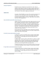
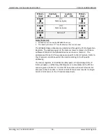
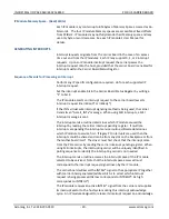
Clock Control Register - (Read/Write, P 018H)
The Clock Control Register is used to select the clock frequency of the
individual IP modules. A “0” (default) selects the 8MHz clock. A “1” selects
the 32MHz clock. A reset will set all bits of this register to “0”.

