INDUSTRIAL I/O PACK SERIES APCe8650
PCI BUS CARRIER BOARD
Acromag, Inc. Tel: 248-295-0310
- 21 -
www.acromag.com
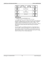
will release its interrupt request upon receiving an active INTSEL* signal from
the carrier. If the IP module is designed to release its interrupt request on
register access the interrupt service routine must access the required register
to clear the interrupt request.
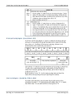
If the IP interrupt stimulus has been removed and no other IP modules have
interrupts pending, the interrupt cycle is completed (i.e. the carrier board
transmits a “Deactivate_INTx” message).
4.
THEORY OF OPERATION
This section describes the basic functionality of the circuitry used on the
carrier board. Refer to Figure 1 APCe8650 Block Diagram as you review this
material.
CARRIER BOARD OVERVIEW
The carrier board is a PCIe bus slave/target board providing up to four IP
module interfaces. The carrier board’s PCIe bus interface allows an intelligent
single board computer (PCI bus Master) to control and communicate with IP
modules that are present on the PCIe bus carrier. IP module field I/O
connections link to field I/O connections on the carrier, which in turn connect
to field electronic hardware connected to the carrier board via ribbon cable.
The PCIe bus and IP module logic commons have a direct electrical connection
(i.e., they are not electrically isolated). However, the field I/O connections
can be isolated from the PCIe bus if an IP module that provides this isolation
(between the logic and field side) is utilized. A wide variety of IP modules are
currently available (from Acromag and other vendors) that interface with
many external devices for digital I/O, analog I/O, and communication
applications.
PCIe Bus Interface
The carrier board’s PCIe bus interface is used to program and monitor carrier
board registers for configuration and control of the board’s modes of
operation (see section 3). In addition, the PCI bus interface is also used to
communicate with and control external devices that are connected to an IP
module’s field I/O signals (assuming an IP module is present on the carrier
board).
The PCI bus interface is implemented in the logic of the carrier board’s PCIe
bus target interface chip. The PCIe bus interface chip implements PCIe
specification version 1.1 as an interrupting slave including 8-bit and 16-bit
data transfers to the IP modules.
32-bit IP data transfers will be treated as
two 16-bit data transfers.
Note that the APCe8650 board is not hot-swappable.


