INDUSTRIAL I/O PACK SERIES APCe8650
PCI BUS CARRIER BOARD
Acromag, Inc. Tel: 248-295-0310
- 14 -
www.acromag.com
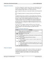
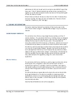
The Configuration Registers are accessed via the Configuration Address and
Data Ports. The most important Configuration Registers are the Base Address
Registers and the Interrupt Line Register, which must be read to determine
the base address, assigned to the carrier and the interrupt request line that
goes active on a carrier interrupt request.
Table 3-2 Configuration Registers
REG
D31
D24 D23
D16 D15
D8
D7
D0
0
Device ID=5901
Vendor ID= 16D5
1
Status
Command
2
Class Code
Rev ID
3
BIST
Header
Latency
Cache
4
Base Addr. Memory Mapped Configuration Registers
5
Base Address for I/O Mapped Configuration Registers
6
PCIBar2:
Base Address for Carrier/IO/ID/INT/Memory Space
7-10
Not Used
11
Subsystem ID
Subsystem Vendor ID
12
Not Used
13
Reserved
14
Reserved
15
Max_Lat
Min_Gnt
Inter. Pin
Inter. Line
Memory Map
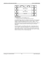
This board occupies a 64M byte block. The 64M byte block of memory
consists of blocks of memory for the ID, I/O, INT and memory spaces
corresponding to four IP modules. In addition, a small portion of the address
space contains registers specific to the function of the carrier board.
The carrier is configured to map this 64M byte block of memory into 32-bit
memory space. The system configuration software will allocate space by
writing the assigned addresses into the corresponding Base Address registers
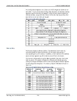
of the Configuration Registers. The memory map for APCe8650 is shown in
Table 3-3.
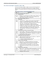
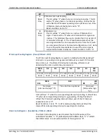
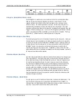
Table 3-3 APCe8650 Carrier Board Memory Map
P
(Hex)
High Byte
D15 D08
Low Byte
D07 D00
P
(Hex)
0001
Carrier Board Status / Control Register
0000
0003
IP Interrupt Pending Register
0002
0005
IP A Interrupt 0 Select Space
0004
0007
IP A Interrupt 1 Select Space
0006
0009
IP B Interrupt 0 Select Space
0008
000B
IP B Interrupt 1 Select Space
000A
000D
IP C Interrupt 0 Select Space
000C
000F
IP C Interrupt 1 Select Space
000E
0011
IP D Interrupt 0 Select Space
0010


