background image

ASD SERIES INSTALLATION AND OPERATION MANUAL 

13 

 AC LINE INPUT FUSING 

The  drive  does  not  contain  line  fuses.  Most  electrical  codes  require  that  each  ungrounded  conductor  contain circuit  protection.  Do  not  fuse 
neutral or ground connections. It is recommended to install a  fuse (Littelfuse 312/314, Buss ABC, or equivalent) or a circuit breaker in series 
with each ungrounded conductor. Do not fuse motor leads. For the recommended fuse size, see Table 2 on page 7. 


CAUTION! 

Do not fuse neutral or grounded connections. 


 ELECTRICAL CONNECTIONS 

Wire the drive in accordance with the National Electrical Code requirements and other local codes that may apply to the application. 


WARNING!

 Read Safety Warnings, on page 5, before using the drive. Disconnect main power before making connections to the drive.     

To avoid electric shock, be sure to properly ground the drive. 


WARNING! HIGH VOLTAGE! REMOTE CONNECTIONS OF POTENTIOMETER, SWITCHES, ETC., MAY HAVE WIRING THAT IS AT 

LINE POTENTIAL. 

 
Be sure to properly fuse each AC Line conductor that is not at ground potential. Do not fuse neutral or grounded conductors.  A separate AC 
Line switch or contactor must be wired as a disconnect so that each ungrounded conductor is opened. For fuse or circuit breaker selection, see 
Table 1 on page 7. Also see Section 6. 
 
To maintain the watertight integrity of the drive, be sure to use suitable liquidtight fittings and wiring which are appropriate for the application. 
Liquidtight Fittings Kits are available for all models. 
 
The drive is designed with a hinged case so that when the front cover is open, all wiring stays intact. To open the cover, the four screws must 
be loosened so they are no longer engaged in the case bottom. After mounting and wiring, close the cover making sure that the wires do not 
get caught or crimped as the cover is closed. Tighten the four screws so that the gasket is slightly compressed. The recommended tightening 
torque is 12 in-lbs (14 kg-cm) 

– do not overtighten. See Figures 7 and 8 on pages 11 and 12 for the tightening sequence. 


Application Note:

 To avoid erratic operation, do not bundle the AC Line and motor wires with each other or with  wires from signal following, 

start/stop contacts, or any other signal wires. Also, do not bundle motor wires from multiple drives in the same conduit. Use shielded cables on 
all signal wiring over 12" (30 cm). The shield should be earth grounded on the drive side only. Wire the drive in accordance with the National 
Electrical Code requirements and other local codes that may apply. 
 

TABLE 3 

DRIVE TERMINAL BLOCK WIRE SIZE AND TIGHTENING TORQUE SPECIFICATIONS 

Terminal 

Block 

Description 

Model 

Maximum 

Wire Size (Cu) 

Recommended 

Tightening Torque 

AWG 

mm

2


in-lbs 

kg-cm 

TB1 

AC Line Input and 

Motor Wiring 

ASD-24D 

12 

3.3 

ASD-27D, 29, 29 (1P), 45, 48 

12 

3.3 

12 

14 

TB2 

Run/Fault Relay 
Output Contacts 

ASD-24D, 27D, 29, 29 (1P), 45, 48 

14 

2.08 

3.5 


7.1 

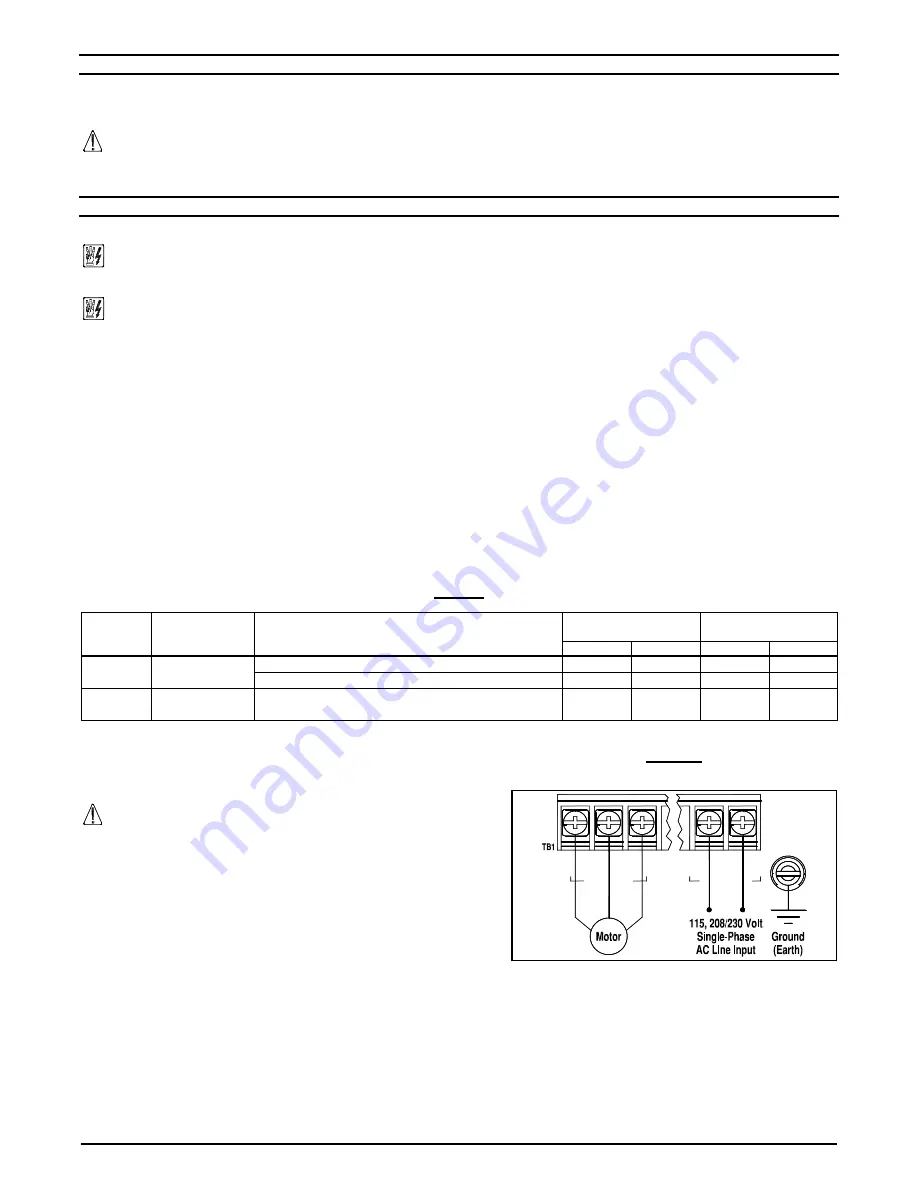
– AC LINE INPUT CONNECTION 

Connect  the  AC  Line  input  to  Terminal  Block  TB1.  See  Figures  9  and  10  on 
pages 13 and 14. 


CAUTION!

 The rated AC Line voltage of the drive must match the actual 

AC Line input voltage. On ASD-24D, 27D the setting of Jumper J1 must match 
the AC Line input voltage. 
 

ASD-24D, 27D:

 Designed to accept 1-phase AC Line input only (Terminals L1, 

L2).  Rated  for  208/230  Volt  AC  Line  input  with  Jumper  J1  set  to  the  "230V" 
position (factory setting). Rated for 115 Volt AC Line input with Jumper J1 set to 
the "115V" position. See Figure 9. 
 

ASD-29  (1P):

  Designed  to  accept  1-phase  AC  Line  input  (Terminals  L1,  L2). 

Rated for 208/230 Volt AC Line input only. See Figure 9. 
 

ASD-29:

 Designed to accept 1-phase (Terminals L1, L2) or 3-phase (Terminals L1, L2, L3) AC Line input. Rated for 208/230 Volt AC Line input 

only. See Figure 10 on page 14. 
 

ASD-45, 48:

 Designed to accept 3-phase AC Line input only (Terminals L1, L2, L3). Rated for 400/460 Volt AC Line input only. See Figure 10 

on page 14. 


FIGURE 9 

ASD-24D, 27D, 29 (1P) 

AC LINE INPUT, MOTOR, AND GROUND CONNECTIONS 










Содержание ACME SYNC ASD Series

Страница 1: ...TE The drive is factory set for 60 Hz motors For 50 Hz motors see Section 10 4 on page 15 See Safety Warnings on page 5 LISTED IND CONT EQ 70ZA 3 RoHS This Manual Covers Models ASD 24D 27D 29 29 1P 45...

Страница 2: ...Hz Motor Operation 15 10 4 2 Setting the Drive for Two Times the Rated Motor RPM 15 10 5 Boost Mode Selection J6 16 10 6 Braking Mode Selection J7 16 10 7 Run Fault Output Relay Operation Selection J...

Страница 3: ...oost Mode Selection J6 16 19 Braking Mode Selection J7 16 20 Run Fault Output Relay Operation Selection J8 16 21 Stop Contact Type Selection J9 16 22 Torque Mode Selection J10 16 23 Switching Frequenc...

Страница 4: ...lt AC Line input and 2 HP maximum with 208 230 Volt AC Line input ASD 29 Designed to accept 1 phase Terminals L1 L2 or 3 phase Terminals L1 L2 L3 AC Line input Rated for 208 230 Volt AC Line input onl...

Страница 5: ...tilated 3 phase AC induction motors will overheat if used beyond a limited speed range at full torque Therefore it is necessary to reduce motor load as speed is decreased Note Some fan cooled motors c...

Страница 6: ...rial Duty Die Cast Aluminum Case with Hinged Cover Available in dark gray finish or FDA approved white finish Simple to Operate Does not require programming Uses trimpots and jumpers which are factory...

Страница 7: ...put Voltage Operating Range Volts AC 208 15 230 15 400 460 Volt AC Line Input Voltage Operating Range Volts AC 380 15 460 15 Maximum Load Current Overload for 2 Minutes 150 Switching Frequency kHz Jum...

Страница 8: ...on See Section 10 2 on page 15 5 Jumper J5 Motor Frequency selection See Section 10 4 on page 19 6 Jumper J12 Switching Frequency and GFCI selection See Section 10 11 on page 16 7 Jumper J6 Adjustable...

Страница 9: ...ee Section 10 5 on page 16 5 Jumper J4 Frequency Multiplier selection See Section 10 4 on page 15 6 Jumper J7 Regeneration or DC Injection Braking See Section 10 6 on page 16 7 Jumper J5 Motor Frequen...

Страница 10: ...15 4 Jumper J6 Adjustable Boost selection See Section 10 5 on page 16 5 Jumper J4 Frequency Multiplier selection See Section 10 4 on page 15 6 Jumper J7 Regeneration or DC Injection Braking See Sectio...

Страница 11: ...should be taken to avoid extreme hazardous locations where physical damage can occur When mounting the drive in an enclosure the enclosure should be large enough to allow for proper heat dissipation s...

Страница 12: ...ASD SERIES INSTALLATION AND OPERATION MANUAL 12 FIGURE 8 ASD 27D 29 29 1P 45 48 MECHANICAL SPECIFICATIONS Inches mm Tighten these screws in the sequence shown to 12 in lbs 14 kg cm...

Страница 13: ...gasket is slightly compressed The recommended tightening torque is 12 in lbs 14 kg cm do not overtighten See Figures 7 and 8 on pages 11 and 12 for the tightening sequence Application Note To avoid e...

Страница 14: ...G All equipment AC Line inputs must be disconnected from the AC power Connect all equipment AC power input lines together and connect them to the H V lead of the hi pot tester Connect the RETURN lead...

Страница 15: ...ut 10 3 AUTOMATIC RIDE THROUGH OR MANUAL START SELECTION J3 Jumper J3 is factory set to the A or AUTO position for Automatic Ride Through If the power is interrupted for up to 2 seconds the drive will...

Страница 16: ...ing Frequency 8 kHz Switching Frequency Factory setting 11 DRIVE OPERATION 11 1 START UP PROCEDURE After the drive has been properly setup jumpers and trimpots set to the desired positions and wiring...

Страница 17: ...generation Protection It is recommended that for very high inertial loads that both the ACCEL and DECEL Trimpots be set to greater than 10 seconds 12 5 DC INJECTION BRAKE TRIMPOT DECEL The drive is fa...

Страница 18: ...which provides indication of a fault or abnormal condition The information provided can be used to diagnose an installation problem such as incorrect input voltage overload condition and drive output...

Страница 19: ...ge Volts DC 0 to 2 5 thru 0 to 25 0 to 5 Signal Offset Trimpot OFFSET Range of SCALE Trimpot Setting 0 40 0 Input Current Range mA DC 4 20 Forward and Reverse Input Switch Types Dry Contact or Open Co...

Страница 20: ...ve for a specific application 14 2 1 SCALE TRIMPOT SCALE The SCALE Trimpot is factory set to run the motor at full speed with a 10 Volt DC analog signal input For a higher analog signal input 25 Volt...

Страница 21: ...ASD SERIES INSTALLATION AND OPERATION MANUAL 21 NOTES...

Страница 22: ...ASD SERIES INSTALLATION AND OPERATION MANUAL 22 NOTES...

Страница 23: ...ASD SERIES INSTALLATION AND OPERATION MANUAL 23 NOTES...

Страница 24: ...uding injury to any person caused by items of our manufacture or sale Some states do not allow certain exclusions or limitations found in this warranty and therefore they may not apply to you In any e...

Отзывы: