Chapter 1
19
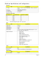
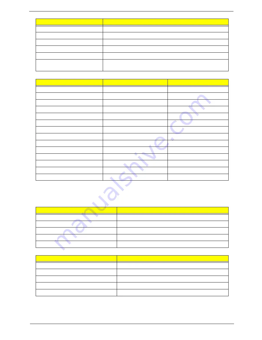
Memory Combinations
NOTE:
Above table lists some system memory configurations. You may combine DIMMs with various
capacities to form other combinations. On above table, the configuration of slot 1 and slot 2 could be
reversed.
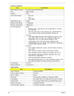
LAN Interface
Bluetooth Interface
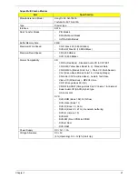
Memory size
0MB (no on-board memory)
DIMM socket number
2 sockets
Supports memory size per socket
2 GB
Supports maximum memory size
4G for 64bit OS (with two 2GB SODIMM)
Supports DIMM type
DDR 2 Synchronous DRAM 667/800 MHz
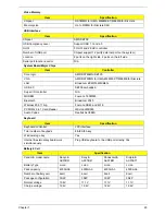
Memory module combinations
You can install memory modules in any combinations as long as
they match the above specifications.
Slot 1
Slot 2
Total Memory
0MB
512MB
512MB
0MB
1024MB
1024MB
0MB
2048MB
2048MB
512MB
512MB
1024MB
512MB
1024MB
1536MB
512MB
2048MB
2560MB
1024MB
0MB
1024MB
1024MB
512MB
1536MB
1024MB
1024MB
2048MB
1024MB
2048MB
3072MB
2048MB
0MB
2048MB
2048MB
512MB
2560MB
2048MB
1024MB
3072MB
2048MB
2048MB
4096MB
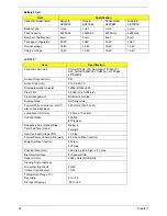
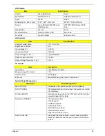
Item
Specification
LAN Chipset
Broadcom BCM5764MKMLG
Supports LAN protocol
IEEE 802.3, 802.3u, 802.3ab, 802.3p
LAN connector type
RJ-45
LAN connector location
RJ-45 (right-rear side on the system)
Features
Gigabit Ethernet
Item
Specification
Chipset
BCM2045
Data throughput
3Mbps
Protocol
IEEE 802.15
Interface
USB
Connector type
mini-USB
Item
Specification
Содержание 5530 5634 - TravelMate - Athlon X2 2.1 GHz
Страница 6: ...VI ...
Страница 14: ...4 Chapter 1 System Block Diagram ...
Страница 36: ...26 Chapter 1 ...
Страница 54: ...44 Chapter 2 ...
Страница 56: ...46 Chapter 2 ...
Страница 64: ...54 Chapter 3 6 Remove the HDD cover as shown 7 Remove the WLAN cover as shown ...
Страница 85: ...Chapter 3 75 6 Turn the upper cover over The upper cover appears as follows ...
Страница 106: ...96 Chapter 3 7 Lift the Thermal Module clear of the Mainboard ...
Страница 112: ...102 Chapter 3 6 Disconnect the left and right Inverter board cables as shown ...
Страница 126: ...116 Chapter 3 3 Replace the RJ 11 cable in its housing ...
Страница 137: ...Chapter 3 127 2 Replace the bracket as shown 3 Replace the single securing screw ...
Страница 140: ...130 Chapter 3 2 Connect the seven cables on the mainboard as shown B C D E F G A ...
Страница 146: ...136 Chapter 3 7 Replace the adhesive strip to secure the cable 8 Replace bracket and secure with provided screw ...
Страница 152: ...142 Chapter 3 ...
Страница 180: ...170 Chapter 5 ...
Страница 196: ...Appendix A 186 ...
Страница 202: ...192 Appendix B ...
Страница 204: ...194 Appendix C ...
Страница 207: ...197 Windows 2000 Environment Test 188 Wireless Function Failure 156 WLAN Board 56 ...
Страница 208: ...198 ...


