37
10 - SECTION E
SOLAR CONTROL UNIT CONTROL MULTI 06 S
HUB RADIATOR PLUS 250 - 400 SOLAR
SOLAR CONTROL UNIT CONTROL MULTI 06 S
10.1 GENERAL
This device is a control unit for the control of solar thermal
systems.
Equipped with 5 outputs (4 load 1 alarm relay), two PWM
outputs, and 4 inputs (probes) it is able to configure and manage
up to 20 different types of solar systems.
By selecting one of the 20 system schemes, the control unit will
automatically manage the outputs and inputs relating to the type
of system selected.
In addition, on the backlit LCD display it will be possible to view
the configuration of the system’s hydraulic diagram, the status
of the outputs, the status of the probes and other numerous
information and data.
The control unit allows you to restore the default data set in the
factory; for more information see parameter P11 ‘UNIT’.
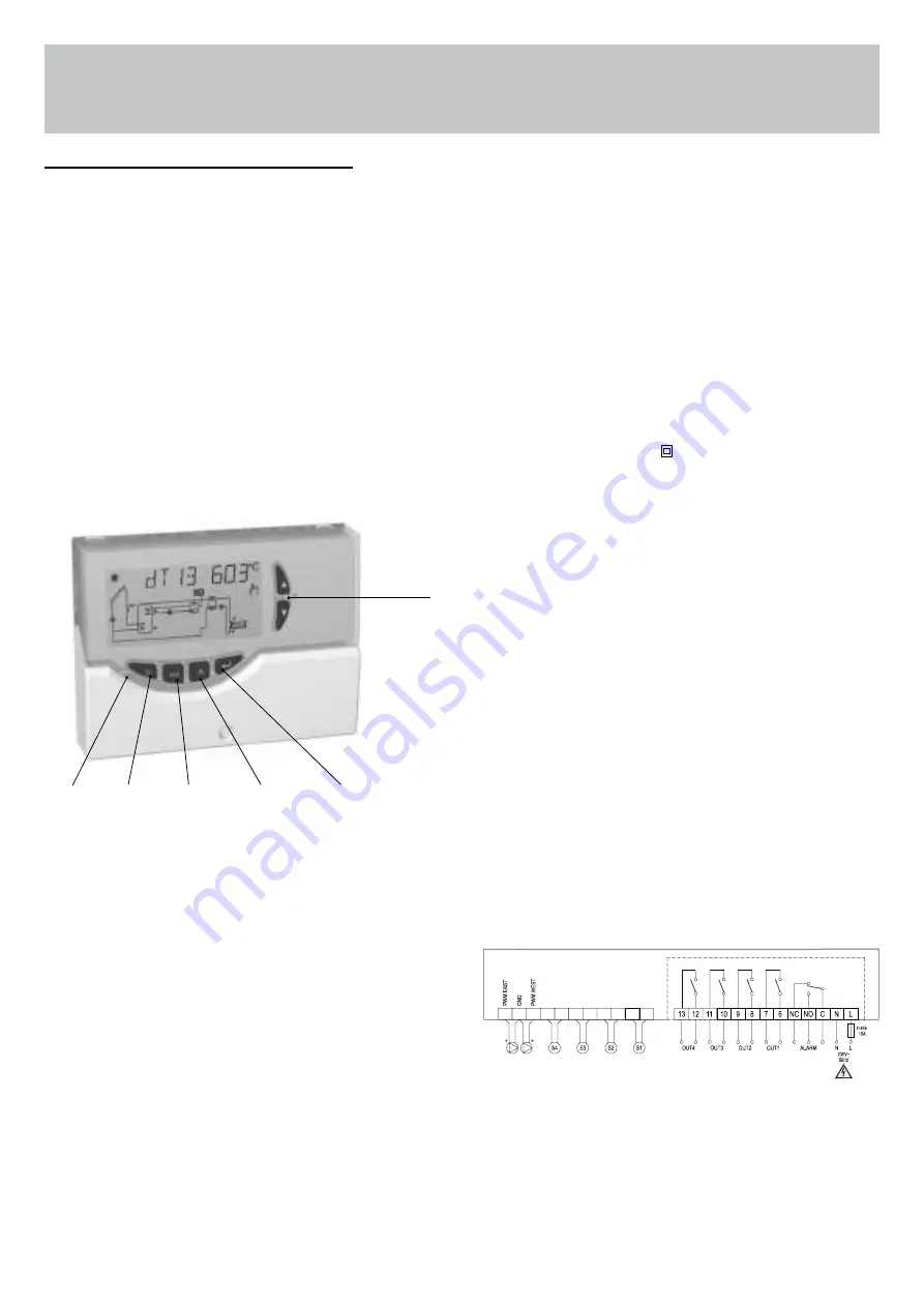
10.2 DESCRIPTION OF THE COMMANDS
KEY
RESET
KEY
MENU
KEY
CANCEL
KEY
MANUAL
KEY
CONFIRM
KEYS OF
SELEZIONE
10.3 TECHNICAL FEATURES
Power supply:
230V~ 50Hz
Absorption:
4 VA
Type of sensors:
4 x Pt1000 Class B DIN
Sensor operation limits:
-50 °C .. +200 °C (collector)
-50 °C .. +110 °C (Boyler)
Temperature reading field:
-40,0 °C .. 260,0 °C
Precision:
± 1¡C
Risolution:
0,1°C (0,2 °F)
Offset:
on S1: ±5.0 °C
on S2: ±5.0 °C
on S3: ±5.0 °C
on S4: ±5.0 °C
Installer password:
0000 .. 9999 (default 0000)
Acoustic signals:
On/Off (default On)
Back light switch-off:
20 sec from last press
logic Rel OUT2:
NOR=N.A. REV=N.C.
non-modifiable logic for schemes
with 2 manifolds (default N.A.)
Logic Rel OUT3:
NOR=N.A. REV=N.C.
(default N.A.)
Logic Rel OUT4:
NOR=N.A. REV=N.C.
(default N.A.)
Output relay contacts capacity:
OUT1 - OUT2 - OUT3 - OUT4: 4x2(1)A max 230V~(SPST)
voltage free contacts
Alarm relay contact capacity: 4(1) A max 230V~(SPDT)
voltage free contacts:
Amplitude: 10V±15%
Frequency: 1KHz
Current:
15mA max.
Resolution: 0.5%
Max allowable length of
PWM cable:
< 5m.
Degree of protection:
IP 40
Type of action:
1
Overvoltage category:
II
Degree of pollution:
2
Index of Tracking (PTI):
175
Protection class
against electric shock:
II
Rated impulse voltage:
2500V
Number of manual cycles:
50000
Number of automatic cycles: 100000
Software class:
A
EMC test voltage:
230V~ 50Hz
EMC test current:
34mA
Distance tolerance exclusion
‘short’ fault mode:
±0,15mm
Ball test temperature:
75 °C
Operating temperature:
0 °C .. 40 °C
Storage temperature:
-10 °C .. +50 °C
Humidity limits:
20% .. 80% RH
non-condensing
Container: Material:
ABS V0 self-extinguishing Signal
Color:
white (RAL 9003)
Dimensions:
156 x 108 x 47 (W x H x D)
Weight:
~ 723 gr. (version with probes)
~ 553 gr. (version without probes)
Fixing:
Wall mounted.
CLASSIFICATION ACCORDING TO REGULATION
2013.811.CE
Class:
not applicable
Contribution to energy efficiency:
not applicable
10.4 ELECTRICAL CONNECTIONS
Make the electrical connections, following the diagram below
WARNING!
Before making any connections, make sure that the
power supply is disconnected.
WARNING!
S1, S2, S3 and S4 are Pt1000 temperature sensors.
For sensor S1 a probe with a range of -50 ° C .. + 200¡C must be
used (probe supplied with gray cable), while for the other


