background image

11

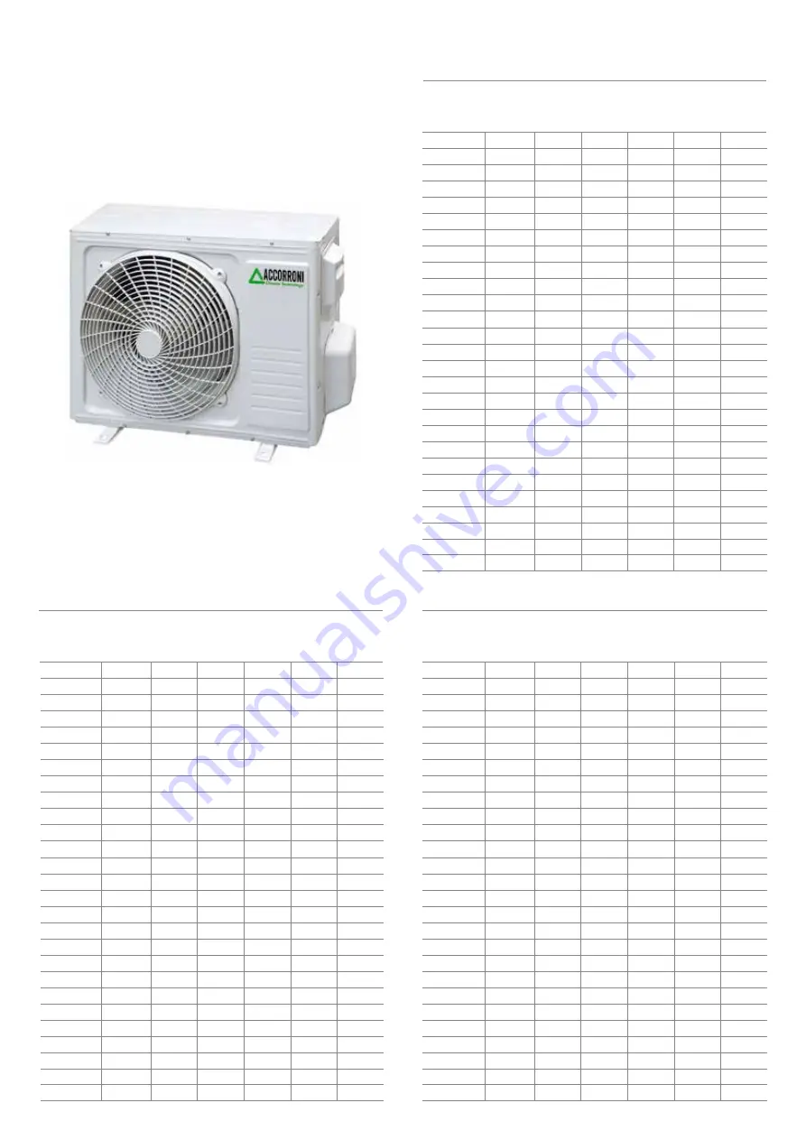
4.4 PERFORMANCE CHARACTERISTICS OF THE OUTDOOR UNIT BOOSTER HR 3.0  

BOOSTER  HR 3.0 - THERMAL POWER DELIVERED

Thermal power delivered kW

Heating water delivery temperature °C

30

1,96

2,.02

2,08

2,14

2,20

2,27

2,33

2,40

2,47

2,54

2,61

2,69

2,76

2,84

2,92

3,01

3,09

3,18

3,27

3,36

3,45

3,55

3,64

3,75

3,85

3,95

Ta 

(°C)

- 10

- 9

- 8

- 7

- 6

- 5

- 4

- 3

- 2

-1

0

1
2
3

4

5
6
7

8

9

10

11

12
13

14

15

35

1,93

1,99

2,05

2,11

2,18

2,24

2,31

2,37

2,44

2,51

2,58

2,65

2,71

2,80

2,87

2,95

3,03

3,11

3,20

3,28

3,37

3,46

3,59

3,64

3,74

3,83

40

1,88

1,94

2,01

2,07

2,13

2,20

2,26

2,33

2,39

2,46

2,53

2,60

2,67

2,74

2,82

2,89

2,97

3,05

3,12

3,20

3,29

3,37

3,45

3,54

3,63

3,72

45

1,80

1,86

1,93

1,99

2,06

2,13

2,19

2,26

2,33

2,40

2,47

2,54

2,61

2,68

2,75

2,82

2,90

2,97

3,05

3,12

3,20

3,28

3,36

3,44

3,52

3,60

50

1,67

1,74

1,81

1,88

1,96

2,03

2,10

2,17

2,24

2,31

2,38

2,45

2,52

2,59

2,66

2,73

2,81

2,88

2,95

3,03

3,10

3,18

3,25

3,33

3,41

3,48

55

1,51

1,58

1,66

1,74

1,81

1,89

1,96

2,04

2,11

2,18

2,26

2,33

2,40

2,47

2,55

2,62

2,69

2,77

2,84

2,91

2,98

3,06

3,13

3,20

3,28

3,35

BOOSTER  HR 3.0 

C.O.P. THERMAL POWER / ABSORBED POWER

Heating water delivery temperature °C

30

2,96

3,04

3,14

3,23

3,32

3,42

3,52

3,63

3,74

3,85

3,96

4,08

4,20

4,33

4,46

4,59

4,73

4,87

5,01

5,16

5,32

5,48

5,64

5,81

5,99

6,17

Ta 

(°C)

- 10

- 9

- 8

- 7

- 6

- 5

- 4

- 3

- 2

-1

0

1
2
3

4

5
6
7

8

9

10

11

12
13

14

15

35

2,59

2,67

2,75

2,81

2,92

3,01

3,10

3,19

3,28

3,37

3,48

3,57

3,67

3,78

3,88

4,00

4,11

4,20

4,35

4,47

4,60

4,73

4,86

5,00

5,15

5,29

40

2,25

2,32

2,39

2,47

2,54

2,62

2,70

2,78

2,86

2,94

3,02

3,11

3,20

3,29

3,38

3,47

3,57

3,66

3,76

3,86

3,97

4,08

4,19

4,30

4,42

4,54

45

1,91

1,98

2,05

2,11

2,19

2,26

2,33

2,40

2,47

2,54

2,67

2,69

2,76

2,84

2,92

3,00

3,08

3,16

3,24

3,33

3,42

3,51

3,60

3,69

3,78

3,88

50

1,59

1,65

1,71

1,78

1,84

1,91

1,97

2,04

2,10

2,17

2,23

2,30

2,37

2,43

2,50

2,57

2,64

2,71

2,78

2,85

2,92

3,00

3,07

3,15

3,23

3,31

55

1,27

1,33

1,39

1,46

1,52

1,58

1,64

1,70

1,76

1,82

1,88

1,94

2,00

2,06

2,12

2,18

2,24

2,30

2,36

2,42

2,48

2,54

2,61

2,67

2,74

2,80

BOOSTER  HR 3.0

ABSORBED ELECTRICAL POWER kW

Heating water delivery temperature °C

30

0,66

0,66

0,66

0,66

0,66

0,66

0,66

0,66

0,66

0,66

0,66

0,66

0,66

0,66

0,66

0,65

0,65

0,65

0,65

0,65

0,65

0,65

0,65

0,64

0,64

0,64

Ta 

(°C)

- 10

- 9

- 8

- 7

- 6

- 5

- 4

- 3

- 2

-1

0

1
2
3

4

5
6
7

8

9

10

11

12
13

14

15

35

0,75

0,75

0,75

0,75

0,75

0,75

0,74

0,74

0,74

0,74

0,74

0,74

0,74

0,74

0,74

0,74

0,74

0,74

0,74

0,73

0,73

0,73

0,73

0,73

0,73

0,72

40

0,84

0,84

0,84

0,84

0,84

0,84

0,84

0,84

0,84

0,84

0,84

0,84

0,84

0,84

0,83

0,83

0,83

0,83

0,83

0,83

0,83

0,83

0,82

0,82

0,82

0,82

45

0,94

0,94

0,94

0,94

0,94

0,94

0,94

0,94

0,94

0,94

0,94

0,94

0,94

0,94

0,94

0,94

0,94

0,94

0,94

0,94

0,94

0,94

0,93

0,93

0,93

0,93

50

1,05

1,06

1,06

1,06

1,06

1,06

1,06

1,06

1,06

1,06

1,06

1,06

1,06

1,06

1,06

1,06

1,06

1,06

1,06

1,06

1,06

1,06

1,06

1,06

1,06

1,05

55

1,19

1,19

1,19

1,19

1,19

1,19

1,20

1,20

1,20

1,20

1,20

1,20

1,20

1,20

1,20

1,20

1,20

1,20

1,20

1,20

1,20

1,20

1,20

1,20

1,20

1,20

Содержание HUB RADIATOR PLUS

Страница 1: ...ted high efficiency heat pump system with direct refrigerant water exchange to produce domestic hot water and heating for medium users with or without solar thermal integration HUB RADIATOR PLUS HUB RADIATOR PLUS SOLAR INSTALLATION MANUAL ...

Страница 2: ...HUB RADIATOR PLUS PLUS SOLAR 400 15 GENERAL INFORMATIONS HUB RADIATOR PLUS 250 400 SOLAR GENERAL WARNINGS The instruction booklet is an integral and essential part of the product and must be kept by the user Carefully read the warnings contained in the booklet as they provide important information regarding the safety of installation use and maintenance Keep the booklet carefully for any further c...

Страница 3: ...ONTROL MULTI 06 S HUB RADIATOR PLUS 250 400 SOLAR 37 10 1 Generality 37 10 2 Description of the commands 37 10 3 Technical features 37 10 4 Electrical connections 37 10 5 Start 38 10 6 Display of temperatures speed and energy produced 38 10 7 Sun Antifreeze display 38 10 8 Installer parameters 39 10 9 Management of anomalies probable causes 47 11 SECTION F WIRING DIAGRAMS HUB RADIATOR PLUS 250 400...

Страница 4: ...recessed the indoor unit is supplied complete with all the appropriate internal copper exchangers auxiliary auxiliary back up and emergencyresistor freonconnections DHWconnections airvent jolly valve safety valve filling cock pressure gauge diverter valve to give priority to the domestic hot water flow switch electronic circulator expansion tank temperature probes 1 4 CONTENT OF THE PACKAGING The ...

Страница 5: ... cable to the outdoor unit 4 Remove the cover of the outdoor unit 5 Connect the terminal cables according to the numbers on the unit terminal block respecting the sections shown in the table 1 6 Secure the cables so that they do not come into contact with parts electric or metal 2 3 INSTALLING THE PIPES FOR THE REFRIGERANT R410A The main cause of refrigerant gas leaks is due to a defect in the fla...

Страница 6: ... allowed without adding refrigerant Minimum allowed length of refrigerant gas Maximum length of refrigerant gas piping Maximum admissible height difference between U E and U I U I Additional refrigerant quantity over 5 meters A B C D E Failure to comply with this application will result in the non ignition by the authorized assistance A INSTALLATION WITHIN 5 METERS Example of installation without ...

Страница 7: ...ig 7 Fig 7 Position the air outlet so that the flow is not hindered in any way In the case of strong wind make sure that the fan works correctly positioning the unit longitudinally along a wall or using a shield If the appliance is to be suspended from an external wall the substrate must comply with the techn specifications The wall where the unit must be installed it must be brick or material of ...

Страница 8: ...e 7 meters of piping between the outdoor and indoor units add 40 g of R410A gas In any case never exceed 15 meters Add only after vacuuming the pipes connecting the 2 units as illustrated in chapter 3 4 after which you can proceed with opening the gas taps mounted on the machine 3 5 EVACUATION Connect the end of the charging hose to the vacuum pump to evacuate the air from the pipes of the indoor ...

Страница 9: ...temperature system return M 1 8 Water mains inlet M 1 2 9 Booster HR gas line refrigeration circuit 1 5 8 Booster 7 8 9 0 3 8 Booster 3 0 10 Liquid line Booster HR refrigerant circuit 1 1 4 Booster 3 0 7 8 3 8 Booster 9 0 11 Forced circulation solar thermal collector delivery M 3 4 12 Forced circulation solar thermal collector return M 3 4 11 12 3 6 7 4 8 9 10 5 1 2 Booster outdoor HR 3 0 7 8 Boos...

Страница 10: ...em filling cock 15 Automatic jolly valve for system air vent 16 Additional heat generator water delivery 17 Additional heat generator water return 18 8 liter system expansion vessel 19 8 liter solar expansion vessel optional 20 Integrative electric heater 2 kW 21 Zone 1 system circulator 22 Zone 2 system circulator optional 23 Mix valve for radiant system optional 24 System safety valve 3 bar 25 U...

Страница 11: ...3 28 3 37 3 48 3 57 3 67 3 78 3 88 4 00 4 11 4 20 4 35 4 47 4 60 4 73 4 86 5 00 5 15 5 29 40 2 25 2 32 2 39 2 47 2 54 2 62 2 70 2 78 2 86 2 94 3 02 3 11 3 20 3 29 3 38 3 47 3 57 3 66 3 76 3 86 3 97 4 08 4 19 4 30 4 42 4 54 45 1 91 1 98 2 05 2 11 2 19 2 26 2 33 2 40 2 47 2 54 2 67 2 69 2 76 2 84 2 92 3 00 3 08 3 16 3 24 3 33 3 42 3 51 3 60 3 69 3 78 3 88 50 1 59 1 65 1 71 1 78 1 84 1 91 1 97 2 04 2...

Страница 12: ... 3 18 3 28 3 37 3 47 3 62 3 67 3 77 3 88 3 99 4 14 4 22 4 34 4 47 4 59 4 47 4 86 5 00 5 14 40 2 18 2 25 2 33 2 40 2 47 2 55 2 62 2 70 2 78 2 86 2 94 3 02 3 10 3 19 3 28 3 37 3 46 3 56 3 65 3 75 3 86 3 96 4 07 4 18 4 29 4 41 45 1 91 1 98 2 05 2 05 2 19 2 26 2 33 2 40 2 47 2 54 2 53 2 69 2 68 2 84 2 92 3 00 3 08 3 07 3 24 3 33 3 42 3 51 3 49 3 69 3 78 3 88 50 1 54 1 60 1 67 1 73 1 79 1 85 1 92 1 98 ...

Страница 13: ...C O P THERMAL POWER ABSORBED POWER Heating water delivery temperature C 30 2 89 3 15 3 64 4 12 4 91 6 30 Ta C 10 7 2 2 7 12 35 2 58 2 81 3 22 3 62 4 24 5 38 40 2 31 2 50 2 84 3 18 3 76 4 61 45 2 04 2 20 2 49 2 76 3 31 3 93 50 1 75 1 89 2 13 2 36 2 76 3 31 55 1 44 1 55 1 75 1 94 2 23 2 71 BOOSTER HR 9 0 INV THERMAL POWER DELIVERED Thermal power delivered kW Heating water delivery temperature C 30 5...

Страница 14: ...oolant line connection R410A Sound power 9 Sound pressure 1 m 10 External temperature operating limits Power supply Max absorbed power Max absorbed Weight 15 45 1 Heating outside air temperature 7 C b d 6 C b w inlet outlet water temperature30 35 C 2 Heating outside air temperature 7 C b d 6 C b w inlet outlet water temperature 40 45 C 3 Heating outside air temperature 0 C b d water temperature in...

Страница 15: ...p in domestic hot water exchanger in copper Solar exchanger surface in copper Pressure drop in copper solar exchanger Type of insulation Insulation thickness Power supply Internal unit accumulation heat loss Degree of protection Shipping weight Operating weight 4 9 DHW WITHDRAWAL TABLE HUB RADIATOR PLUS PLUS SOLAR 400 DESCRIPTION DHW withdrawal at 40 C storage at 55 C inlet water at 10 C DHW withd...

Страница 16: ... HR ONLY HOT 1 2 DHW MIXING VALVE KIT AUXILIARY BASIN FOR INSTALLATION UNDER SHELF EQUIPPED WITH 90 W HEATING CABLE CONDENSATE ANTIFREEZE HEATING CABLE WITH THERMAL SENSOR FACTORY FITTED FLOOR SUPPORT COMPLETE WITH AUXILIARY BASIN EQUIPPED WITH 90 W HEATING CABLE FACTORY MADE HYBRID SYSTEM ELECTRONIC MANAGEMENT KIT WITH CONNECTION SLEEVES FOR ADDITIONAL THERMAL GENERATOR FLEXIBLE ANTI VIBRATION JO...

Страница 17: ...reeze heaters boiler On flashing during the interval count between defrosts the icon is steady on during the phase defrost Flashing on if the entrance digital flow switch is active both with pump ON and with pump OFF On if at least one of the 2 water pumps evaporator pump or pump capacitor is on On if the fans are on On if the relative compressor is switched on is flashing if the compressor is in ...

Страница 18: ... into manual defrost Regarding the use of the remote terminal indications on the display and meaning of the keys do reference to the preceding paragraphs In air air units in case of terminal use remote equipped with NTC probe VICXS610 configuring par CF35 2 the display will show the room air temperature this probe will be used from the controller for temperature control In case of controller remot...

Страница 19: ...orrect defrost cycle generic alarm Code on display A12 Defrost End defrost for Code on display Automatic error alarm maximum time reporting only if the value is within the expected range correct defrost cycle A09 Compressor Condensation Activate open output Automatic thermal alarm start temperature collector alarm relay if the value is within of 110 C Activate buzzer the expected range Flashing ic...

Страница 20: ...rging alarm thermostat 3 Q E thermostat connection 3 Replacement of Q E contact open thermostat connection cable A12 Defrost End defrost 1 Lack of refrigerant gas 1 External Booster Charging error for maximum 2 Extreme outdoor conditions 2 Change of parameters DF03 and DF04 alarm time 3 Condensate drain blocked 3 Make sure that condensation 4 PB3 probe out of range flow out regularly 4 PB3 probe r...

Страница 21: ...etro Descrizione min max udm Risoluzion e ST18 Set point ambiente in chiller ST20 ST21 C F dec int ST19 Differenziale ambiente in chiller 0 0 0 25 0 45 C F Dec int ST20 Set minimo ambiente in chiller 50 0 58 ST18 C F Dec int ST21 Set massimo ambiente in chiller ST18 110 230 C F Dec int ST22 Set point ambiente in p d c ST24 ST25 C F dec int ST23 Differenziale ambiente in p d c 0 0 0 25 0 45 C F Dec...

Страница 22: ...ttivo contatto chiuso 1 Attivo contatto aperto 0 1 12 Allarme termica pompa acqua evaporatore termica ventilatore di mandata 13 Allarme termica pompa acqua condensatore 14 Flussostato condensatore 15 Disabilitato CF09 Configurazione ID2 0 Termica compressore 1 1 Termica ventilatore di condensazione 2 Flussostato evaporatore 3 On off remoto 4 chiller pompa di calore remoto 5 Termica compressore 2 6...

Страница 23: ...ore 3 Funzionamento continuo in uscita 4 20mA 4 Funzionamento su chiamata del compressore 4 20mA 0 4 CO12 Compressore 1 0 Abilitato 1 OFF 0 1 CO13 Compressore 2 parzializzazione 0 Abilitato 1 OFF 0 1 CO14 SET Contaore compressore 1 0 999 Hr 10 Hr CO15 SET Contaore compressore 2 0 999 Hr 10 Hr CO16 SET Contaore pompa acqua ventilatore di mandata unità aria aria 0 999 Hr 10 Hr Unloading evaporator C...

Страница 24: ... 0 Non abilitato 1 Abilitato 0 1 dF17 Ritardo allarme di minima all inversione della valvola 4 vie 0 250 Sec FA09 Massima velocità ventole in estate 30 100 FA10 Set temperatura pressione minima velocità ventole in estate 50 0 58 0 0 0 110 230 50 0 725 C F Bar Psi Dec int Dec int FA11 Set temperatura pressione massima velocità ventole in estate 50 0 58 0 0 0 110 230 50 0 725 C F Bar Psi Dec int Dec...

Страница 25: ...ità relè allarme uscita open collector 0 Uscita senza tensione in condizioni normali con tensione in presenza di allarme 1 Uscita con tensione in condizioni normali senza tensione in presenza di allarme 0 1 AL19 Sonda per allarme antigelo 0 Legato ai parametri Ar16 in chiller Ar17 in p d c 1 Su sonda Pb1 2 Su sonda Pb2 3 Su sonda Pb3 4 Su sonda Pb4 0 4 AL20 Numero massimo di interventi ora allarme...

Страница 26: ...TO THE USER The user must be instructed on the use and operation of his solar system in particular Deliver these instructions to the user as well as the others documents relating to the device inserted in the envelope contained in the packaging The user must keep this documentation in order to have it available for any further consultation Remember that in compliance with the regulations in force ...

Страница 27: ...L DATA PLATE The technical data plate is placed on the side wall of the appliance Tampering removal lack of identification plates or anything else that does not allow the safe identification of the product makes any installation and maintenance operation difficult MOTHER COMPANY NAME Made in____________________ MATR Anno____________ solar collector MODELLO DIMENSIONS OF THE COLLECTOR xxx mt GROSS ...

Страница 28: ...xtra Clear AR Hardened 3 2 mm anti reflective Alluminum Selective TITAN titanium oxide 93 8 3 2 6 204 SELECTIVE HX 42 0 2 40 3 18 2 52 0 797 130 1 70 SELECTIVE H 32 0 1 82 3 53 1 95 0 759 100 1 42 DESCRIPTION Weight Case color Case material Isulation thiskness Glass type Net absorbent surface Coefficient of loss Total collector area Absorbent plate material Surface treatment Efficiency opening η0 ...

Страница 29: ... do not have an imposed direction of circulation This means both connection diagrams represented in the two figures 10 and 11 of this page are admissible Obviously in the installation of several collectors in series and or in parallel once a direction of circulation has been chosen for a collector it must be the same for all the other collectors in the system Fig 10 Fig 11 Total dimensions 7600 mm...

Страница 30: ... PROTECTION WALL A further possibility of protection for works on sloping roofs up to 60 starting from a fall height of 3 m are the roof protection walls The vertical distance between the work station and the guard must be a maximum of 5 m The protective walls must protrude laterally by at least 2 m FALL SAFETY EQUIPMENT If the scaffolding or the roof protection wall are not suitable it is possibl...

Страница 31: ...provide a pressure reducer if the network pressure exceeds 6 bar POSITIONING When choosing the place to install the appliance follow the following safety instructions Place the appliance in places where it is possible to prevent access by children as a potential source of danger to their safety Make sure that the fixing is carried out as illustrated in this manual Make sure there are no high tempe...

Страница 32: ... expansion vessels for vacuum systems vary according to the number of collectors installed the table below shows the recommended values for the expansion vessels to be included in the system Description Dimension ___________________________________________________________________________________________ Till a 3 collectors 12 liters _________________________________________________________________...

Страница 33: ...the boiler probe on center of the solar coil and the integration probe at the top of the boiler Adjust the flow rate of the closed circuit by acting on the regulator flow rate 5 and or on the speed of the solar pump until the value indicated in the table below is reached 8 5 WIRING DIAGRAM FOR PRESSURE RESET FLOW ADJUSTMENT Panels Flow 1 1 7 2 3 3 3 5 4 6 7 5 8 3 6 10 U M N l min 1 8 4 5 6 7 2 3 9...

Страница 34: ...elp of a qualified installer It is absolutely forbidden not to adequately fix the frame to the underlying structure It is absolutely forbidden to put outside or to the elements anything that is not specifically suitable for the outside such as kettles electrical equipment expansion vessels etc ELENCO ANOMALIE POSSIBLE CAUSES POSSIBLE SOLUTIONS Loss of pressure in the manifold circuit Loss of any j...

Страница 35: ...ystem through a 3 way ball valve When the valve is in the closed position normal circulation is interrupted and it is possible to use the side tap to load the system There is a second side tap for draining The proximity of the 2 taps facilitates operations by minimizing the section between loading and unloading The flow rate is indicated by the appropriate sliding cursor the feedback is immediate ...

Страница 36: ... with the fluid The air is collected in the upper area of the deaerator tube and can be eliminated through the appropriate purge during the operation of the system Unscrew the knurled ring no more than half a turn This operation must be done occasionally DANGER OF BURNS to avoid direct leakage of the liquid given the high operating temperature it is advisable to connect a tube to the appropriate e...

Страница 37: ...T2 NOR N A REV N C non modifiable logic for schemes with 2 manifolds default N A Logic Rel OUT3 NOR N A REV N C default N A Logic Rel OUT4 NOR N A REV N C default N A Output relay contacts capacity OUT1 OUT2 OUT3 OUT4 4x2 1 A max 230V SPST voltage free contacts Alarm relay contact capacity 4 1 A max 230V SPDT voltage free contacts Amplitude 10V 15 Frequency 1KHz Current 15mA max Resolution 0 5 Max...

Страница 38: ...fy the correctness of the connections made 10 6 DISPLAY OF TEMPERATURE SPEED AND ENERGY PRODUCED The control unit will normally show on the alphanumeric display the temperature detected by the connected probes the speed in of the collector pumps connected to the PWM outputs E and W and the quantity of energy produced The speed of the EAST manifold PWM pump is shown on the display with EFX while th...

Страница 39: ...aller parameters mode all the outputs are disabled All the default values indicated are to be considered indicative as they may vary according to the version and without notice PRESS KEY 8 FROM THE HOME SCREEN THE DISPLAY SHOWS PWD 0000 ENTER THE CURRENT PASSWORD THE FIRST INSTALLER PARAMETER IS DISPLAYED THROUGH THE ARROWS o IT IS POSSIBLE TO SCROLL CYCLICALLY BETWEEN THE INSTALLER PARAMETERS P1 ...

Страница 40: ...ermostats hysteresis 10 9 OPERATING LOGICS ATTENTION The following control logics must be applied to all the diagrams illustrated below CONTROL LOGIC IN ABC ABC MANUAL T ABC 1 0 MANUALE C The control logic relating to the ABC function commands replaces the differential control The controls relating to the Maximum and Safety temperatures are always active The supplementary source in ABC mode is swi...

Страница 41: ...mp on the 2nd boiler Control logic P2 THERMAL DATA SETTING Using this parameter you can set the thermal data relating to the selected system The control unit is supplied with pre set thermal data for optimal operation The modification of these values must be carried out by qualified personnel SELECTED PARAMETER P2 PRESS THE KEY 8 THROUGH THE ARROWS or IT IS POSSIBLE TO SCROLL CYCLICALLY BETWEEN TH...

Страница 42: ...0 0 C 2 0 C HY34 0 5 25 0 C 2 0 C HY43 0 5 25 0 C 2 0 C HY42 0 5 25 0 C 4 0 C HY13 0 5 25 0 C 2 0 C WARNING It is not possible to set the Hysteresis HY to a value higher than that of the relative Differential ΔT since the value of the Hysteresis is bound to the value of the Differential decreased by 1 C If you want to increase the hysteresis value you must first Increase the value of the Different...

Страница 43: ...ature TAH minus 3 C if you want to decrease the value of the integration temperature TAH below the value of the Economy TEC temperature set you will first have to decrease the value of the Economy TEC temperature and then act on the integration temperature TAH ABC Auto Boiler Control temperature on probe S3 Data Adjustment range Default TABC 20 C 80 0 C 30 C P3 MANAGEMENT OF ANTI FREEZE PARAMETERS...

Страница 44: ...ctivates the connected loads according to the configured scheme activating all the available outputs in sequence for 10 seconds each including the alarm relay and the relative buzzer The test sequence in multiples of 5 can be set using the only parameter present TMR The activation of the test will be signaled on the display with the lighting up of the TIMER icon ATTENTION The activation of the ala...

Страница 45: ...the Maximum Temperatures is increased to a value higher than that of the Recooling Temperature TR this is automatically set to the highest maximum temperature value 1 C The same considerations apply to the TR Recooling temperature compared to the TAH Integration temperature Temperature differential of Recooling TR Data Adjustment range Default ΔTR 6 C 15 C 8 C Activation Deactivation of function R...

Страница 46: ...0 C 90 0 C 10 0 C Enable Disable min Temperature limitation Data Adjustment range Default MTEN 0 1 0 Note with 0 the minimum collector temperature limitation function is deactivated while with 1 it is activated P14 COLLECTOR RESET TEMPERATURE With this parameter it is possible to set the temperature value T_SE T_SW for resetting the collector pump if the TS_2 safety temperature has intervened in o...

Страница 47: ...licy of manufacturer s warranty The full text of the guarantee is available from the seller on request MANAGEMENT OF ANOMALIES AND POSSIBLE CAUSES GESTIONE ANOMALIE E PROBABILI CAUSE ANOMALY POSSIBLE CAUSE During normal operation the control unit shows the symbol on the display and emits an acoustic signal characterized by a series of beeps The probe that generated the problem flashes The control ...

Страница 48: ...ump switch O I OFF ON DR resistance diverter EMERGENZA I I I INTEGRAZIONE ICS solar control unit switch O I OFF ON LEGEND M1 terminal block Booster 1 M2 terminal block Booster 2 Pb1 technical water probe Pb3 battery probe Booster Stc compressor thermal probe Tr transformator 230V 12V R1 electrical resistance relay RD diverter relay RP system pump relay RT voltage mounting relay 3 RR electrical res...

Страница 49: ...49 11 2 Wiring diagram HUB RADIATOR PLUS SOLAR 250 with double external Booster model 7 8 only one direct circulation unit ...

Страница 50: ...50 11 3 Wiring diagram HUB RADIATOR PLUS SOLAR 250 with double external Booster model 7 8 3 0 only one direct circulation group ...

Страница 51: ...51 11 4 Wiring diagram HUB RADIATOR PLUS SOLAR 250 with double external booster model 7 8 one direct and one mixed circulation group ...

Страница 52: ...52 11 5 Wiring diagram HUB RADIATOR PLUS SOLAR 250 with double external Booster model 7 8 3 0 one direct and one mixed circulation group ...

Страница 53: ...53 11 6 Wiring diagram HUB RADIATOR PLUS SOLAR 250 with external Booster model 7 8 only one circulation group ...

Страница 54: ...54 11 7 Wiring diagram HUB RADIATOR PLUS SOLAR 250 with external Booster model 3 0 only one circulation group ...

Страница 55: ...55 11 8 Wiring diagram HUB RADIATOR PLUS SOLAR 250 with single external Booster model 9 0 inverter only one circulation group ...

Страница 56: ...56 11 9 Wiring diagram HUB RADIATOR PLUS SOLAR 250 with single external Booster model 9 0 inverter one direct and one mixed circulation group ...

Страница 57: ...erter valve 38 Inverter solar pump 39 Solar system safety group forced circulation 1 Booster HR 7 8 only hot 2 Technical storage unit 250 liters 3 Domestic hot water delivery 4 Domestic cold water delivery 5 Electric command and control panel 6 System technical water delivery high temperature 7 System technical water return high temperature 8 Mechanical Y filter 9 Water mains volumetric meter 10 W...

Страница 58: ... 9 0 heating only inverter 2 Technical storage unit 250 liters 3 Domestic hot water delivery 4 Domestic cold water delivery 5 Electric command and control panel 6 Mechanical Y filter 7 Volumetric meter for aqueduct 8 Water mains pressure reducer 9 Water mains sand trap filter Winter air conditioning and DHW production system consisting of an indoor unit HUB RADIATOR PLUS SOLAR 250 equipped with an...

Страница 59: ...or substance restriction harmful RoHS and waste electrical and electronic equipment WEEE complies with the provisions of the European Directive EN 378 Cooling systems e heat pumps safety and environmental protection requirements complies with the provisions of the European Directive 94 42 EEC on the degree of efficiency and comply with the EC Construction Products Directive and meet the requiremen...

Страница 60: ...titolo puramente indicativo la A2B Accorroni E G S r l si riserva di apportare eventuali modifiche senza alcun preavviso web site www accorroni it e mail a2b accorroni it A2B Accorroni E G s r l Via d Ancona 37 60027 Osimo An Tel 071 723991 ...

Отзывы: