Introducing the BIOS
User’s Manual
4-11
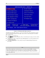
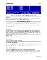
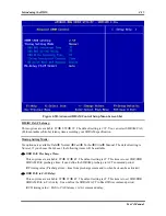
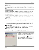
Figure 4-4B
.
Advanced BIOS Features Setup Menu Lower Screen Shot
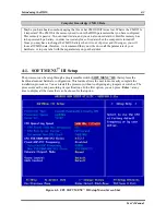
Quick Boot:
Two options are available: Disabled or Enabled. The default setting is
Enabled
. Select
Enabled
to skip
memory test then you can enjoy the convenience of quick boot function.
How to use the Quick Boot function?
When you start to get in the boot sequence, press <
F6
> key one time, then you can see the “
Select
First Boot Device
” menu show up. Choose the first boot device you want then press <
Enter
> key to
continue the boot sequence.
Boot Device Priority:
1st Boot Device:
When the computer boots up, the BIOS attempts to load the operating system from these items: floppy
disk drive A, LS120, ZIP100 devices, hard drive C, SCSI hard disk drive or CD-ROM. The BIOS will
automatically detect the boot devices exist in the system, then it will display the result. At that time, you
can select the device that you want to use it as the 1st boot device.
2nd Boot Device:
Description is the same as the “
1st Boot Device
”.
3rd Boot Device:
Description is the same as the “
1st Boot Device
”.
Try Other Boot Other Devices:
Two options are available: Yes or No. The default setting is
Yes
. This setting allows the BIOS to try to
boot devices other than the three which are listed in the above 1st, 2nd and 3rd Boot Devices. If you set to
Disabled, the BIOS will boot from only the three kinds of boot devices that are set above.
S.M.A.R.T. for Hard Disks:
Two options are available: Disabled or Enabled. The default setting is
Disabled
. SMART
(
S
elf-
M
onitoring
A
nalysis and
R
eporting
T
echnology) is a techniques which warns users of the HDD’s
defects and informs the users to transfer HDD’s data to other places. Therefore, this technique results in
improving the confidence in data preservation and the HDD itself. Therefore, if you make sure your HDD
has supports this feature, then set this item to Enabled. This allows the operating system to take the
necessary precautions and warn the user. For detailed information of your HDD specs, please read the
Содержание SR7-8X
Страница 2: ......
Страница 32: ...Chapter 2 SR7 8X 2 4 2 4 Layout Diagram for SR7 8X Figure 1 1 SR7 8X motherboard component location ...
Страница 82: ...Chapter 4 SR7 8X 4 34 ...
Страница 92: ...Appendix C SR7 8X C 4 ...
Страница 102: ...Appendix F SR7 8X F 6 ...
Страница 114: ...Appendix I SR7 8X I 4 ...

