Chapter 3
SR7-8X
3-14
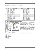
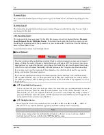
(12). D11: 5V Standby LED
D11 will light up after the power switch is pressed,
this LED will show you the 5V standby power
situation.
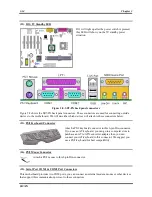
Figure 2-8. SR7-8X back panel connectors
Figure 2-8 shows the SR7-8X back panel connectors. These connectors are used for connecting outside
devices to the motherboard. We will describe which devices will attach to these connectors below.
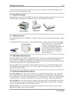
(13). PS/2 Keyboard Connector
Attach a PS/2 keyboard connector to this 6-pin Din-connector.
If you use an AT keyboard, you can go to a computer store to
purchase an AT to ATX converter adapter, then you can
connect your AT keyboard to this connector. We suggest you
use a PS/2 keyboard for best compatibility.
(14). PS/2 Mouse Connector
Attach a PS/2 mouse to this 6-pin Din-connector.
(15). Serial Port COM1 & COM2 Port Connectors
This motherboard provides two COM ports, you can connect an external modem, mouse or other devices
that support this communication protocol to these connectors.
Содержание SR7-8X
Страница 2: ......
Страница 32: ...Chapter 2 SR7 8X 2 4 2 4 Layout Diagram for SR7 8X Figure 1 1 SR7 8X motherboard component location ...
Страница 82: ...Chapter 4 SR7 8X 4 34 ...
Страница 92: ...Appendix C SR7 8X C 4 ...
Страница 102: ...Appendix F SR7 8X F 6 ...
Страница 114: ...Appendix I SR7 8X I 4 ...


