Introduction of the BIOS
3-33
User’s Manual
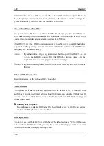
Soft-Off by PWR-BTTN:
Two options are available: Instant-Off and Delay 4 Sec.. The default setting is
Instant-Off
.
Pressing the power button for more than four seconds forces the system to enter the Soft-Off
state when the system has "hung".
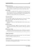
Wake-Up by PCI card:
Two options are available: Enabled and Disabled. Default setting is
Disabled
. This item can
let you wake-up your computer by PCI devices. For instance, if you had installed a PCI LAN
card with Wake-Up on LAN capability, then you could wake-up your computer from
another computer via a network by sending a wake-up frame signal. This feature also allows
the PCI card built-in hardware function to support the wake up function without special
cables connected to the motherboard.
Note
This feature needs a specific network interface, this is optional. Also your ATX power
5V standby power must with at least 720mA capability.
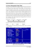
Power On by Ring:
Two options are available: Enabled and Disabled. Default setting is
Disabled
. If you connect
an external modem to the onboard serial port, the system will be turned on when a telephone
ring-up occurs.
Resume by Alarm:
Two options are available: Enabled and Disabled. Default setting is
Disabled
. The RTC
alarm can turn on the system. You can set Date (of month) and Time (hour, minute, and
second) when you set this item to
Enabled
.
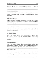
Reload Global Timer Events
When one of the specified events occur, the count down made for entry in power saving
mode goes back to zero. Since the computer will enter a power saving mode only after an
inactivity delay specified (time specific for Doze, Standby and Suspend modes) and after it
has no activity, during this time period, any event will cause the computer to re-count the
time elapsed. Resume events are operations or signals that cause the computer to resume
Содержание AB-CX6
Страница 2: ......
Страница 13: ...Introduction of CX6 Features 1 9 User s Manual 1 3 Layout Diagram Figure 1 1 Motherboard component location ...
Страница 14: ...1 10 Chapter1 CX6 1 4 The System Block Diagram Figure 1 2 System diagram of the Intel 820 chipset ...
Страница 78: ...3 44 Chapter3 CX6 ...
Страница 84: ...B 4 Appendix B CX6 ...
Страница 90: ...D 4 Appendix D CX6 ...
Страница 96: ...E 6 Appendix E CX6 ...
Страница 104: ...G 4 Appendix G CX6 ...
Страница 110: ...H 6 Appendix H CX6 ...

